A detailed explanation of MCS-51 MCU interrupt system
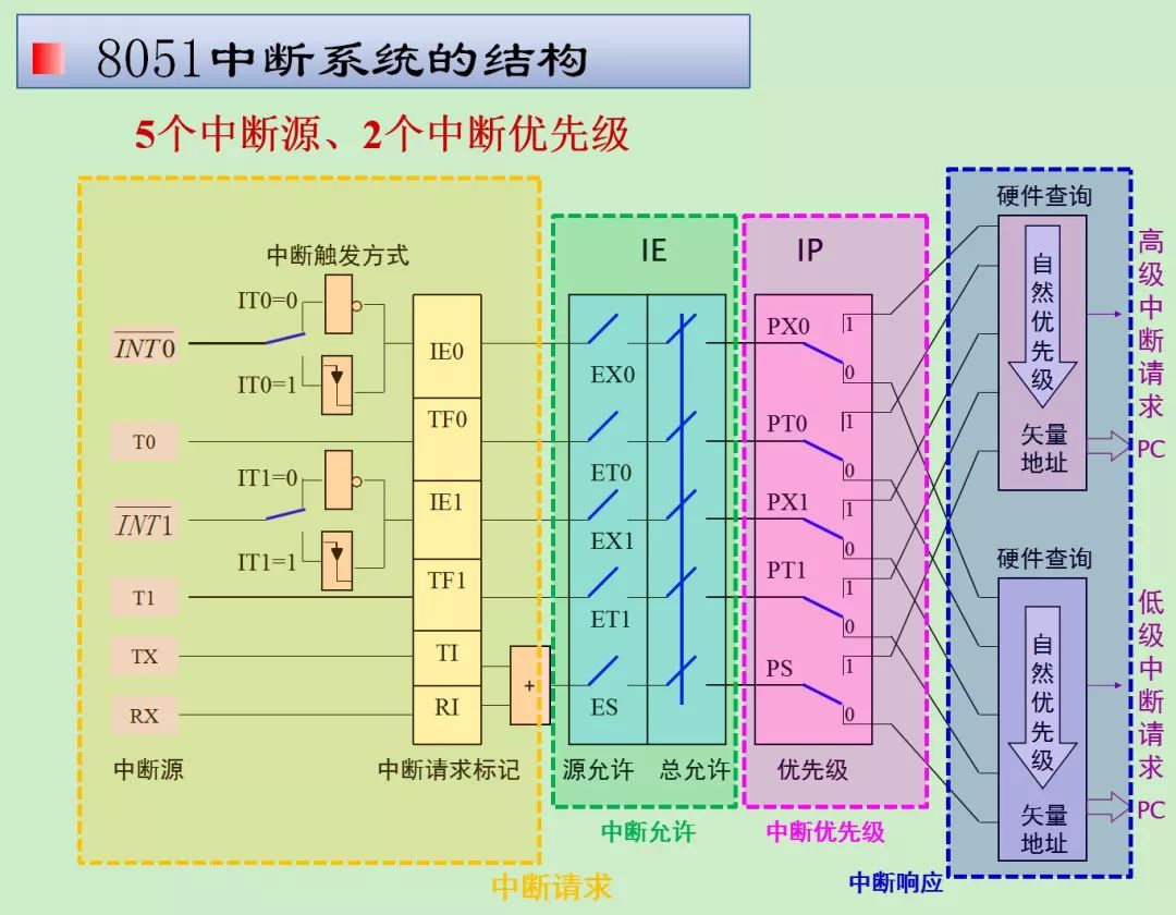
MCS-51 interrupt system: 5 interrupt sources (two external interrupts, two timers, one serial port), 2 priority levels
Interrupt related concepts
Interrupt: When the CPU is processing something, an emergency event that occurs outside or inside the microcontroller requests the CPU to deal with it immediately, so the CPU temporarily suspends the current work and transfers to deal with this emergency event. After the processing is completed, return Go to the place where it was originally suspended and continue the original work.
Interrupt process
Interrupt occurrence: When the CPU is processing an event A, another event B occurs and requests the CPU to process it quickly;
Interrupt response and interrupt service: The CPU temporarily interrupts the current work and transfers to process event B (the priority of B is higher than A);
Interrupt return: After the CPU finishes processing event B, return to the place where event A was interrupted to continue processing event A;
Interrupt source (interrupt request source): a component that can issue an interrupt request to the CPU.
Interrupt system structure
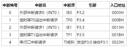
External interrupt 0 and 1: Interrupt request is generated at low level or the falling edge of the pulse;
Timer/counter 0 and 1: An interrupt request is generated when the count value changes from FF to 00; (timing function: counting pulse comes from on-chip; counting function: counting pulse comes from off-chip);
Serial port: an interrupt request is generated when sending or receiving 1 byte of data;
Interrupt control
4 special function registers to implement interrupt control: • Interrupt enable register IE • Interrupt priority register IP • Timer/counter and external interrupt control register TCON • Serial control register SCON
Interrupt enable register IE
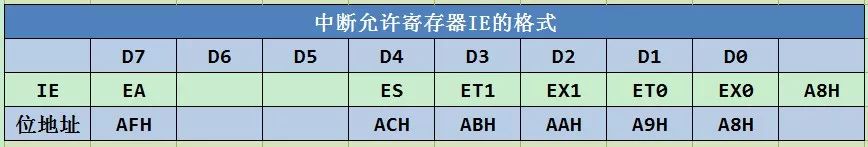
EA interrupt enable master control bit. 0 prohibits, 1 allows.
ES serial interrupt enable control bit. 0 prohibits, 1 allows.
ET1 Timer counter 1 interrupt enable control bit. 0 prohibits, 1 allows.
EX1 External interrupt 1 enable control bit. 0 prohibits, 1 allows.
ET0 timer counter 0 interrupt enable control bit. 0 prohibits, 1 allows.
EX0 External interrupt 0 enable control bit. 0 prohibits, 1 allows.
Interrupt priority register IP
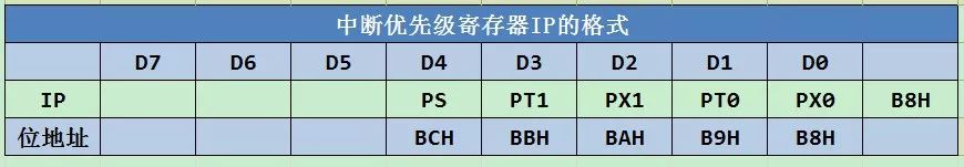
PX0 External interrupt 0 priority control bit. 1 is high, 0 is low
PT0 is the priority control bit of timer interrupt 0. 1 is high, 0 is low
PX1 External interrupt 1 priority control bit. 1 is high, 0 is low
PT1 is the priority control bit of timer interrupt 0. 1 is high, 0 is low
PS priority control bit of serial interrupt. 1 is high, 0 is low
Serial port control register SCON
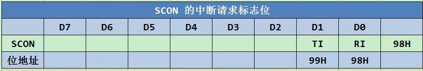
TI: Serial port sends interrupt flag, use software to clear TI flag in response to interrupt
RI: Serial port receiving interrupt flag, use software to clear the RI flag when responding to the interrupt
Timer/counter control register TCON
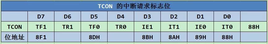
External interrupt trigger mode bit IT0, IT1 (ITx)
ITx = 0 Triggered at low level, IEx is not automatically cleared after responding to interrupt ITx = 1 Triggered on the falling edge of pulse, IEx is automatically cleared after responding to interrupt
External interrupt request 0/1 interrupt request flag IE0, IE1
Timer/counter T0/T1 overflow interrupt request flag TF0/TF1 (TFx)
After starting the T0/T1 count, count from the initial value by 1 until the highest bit overflows, the hardware sets TFx to "1" and requests an interrupt from the CPU. TFx is automatically cleared to 0 after responding to the interrupt;
TR0, TR1 have nothing to do with interrupts, only with timer/counter T0/T1;
Interrupt response
The interrupt response is the response of the CPU to the interrupt request issued by the interrupt source.
Interrupt response conditions
The CPU opens interrupts, that is, the interrupt enable total control bit EA in the interrupt enable register IE = 1; the interrupt source issues an interrupt request; the interrupt enable bit of the interrupt source is 1; no interrupts of the same or higher priority are executing;
Interrupt response process
A long call instruction LCALL addr16 is automatically generated by the hardware according to the type of interrupt source. The CPU executes LCALL addr16.
Interrupt response time
The response time is within 3~8 machine cycles; the shortest response time: query the interrupt request flag (T) + LCALL (2T);
Interrupt response process
Set the corresponding priority status trigger to 1 (blocking the subsequent same-level or low-level interrupts), execute the hardware LCALL instruction (PC is pushed into the stack, the interrupt service program entry address is sent to the PC), execute the interrupt service program PS: write interrupt service program Note: interrupt service The program entry stores instructions LJMP or AJMP; site protection and site recovery.
Interrupt return
The last command is RETI, the function is:
Bounce the breakpoint from the stack to the PC, and the CPU continues to execute from the original breakpoint. Clear the corresponding priority state trigger to 0 and restore the original working state
8051 interrupt program design
Basic flow of interrupt service program
Close interruption: In order to prevent the entry of a higher level of interruption at this time, so as to avoid interruption of the execution process of the field protection.
On-site protection: The so-called on-site refers to the data or state in some registers and memory cells in the microcontroller at the moment of interruption. In order to prevent the execution of the interrupt service routine from destroying this data or state, so as not to affect the operation of the main program after the interrupt returns, they need to be sent to the stack for storage.
Open interrupt: In order to allow more advanced interrupt entry. In this way, in addition to on-site protection and on-site recovery, the interrupt processing process still allows interrupt nesting functions.
Interrupt handling
Close interruption: In order to prevent the entry of a higher level interruption at this time, so as to avoid interruption of the execution process of on-site recovery.
On-site restoration: After the interrupt processing is over, before returning to the main program, pop the saved on-site content from the stack to restore the original content in those registers and storage units
Open interrupt: In order to allow more advanced interrupt entry. After the scene is restored, the nested function is still allowed to be interrupted.
Interrupt return: It must be the return instruction RETI. After the CPU has executed this instruction, it clears the priority status trigger set to "1" when responding to the interrupt to "0", and then pops the two-byte breakpoint address on the top of the stack from the stack to the program counter PC , The first byte popped is sent to PCH, the second byte is sent to PCL, and the CPU re-executes the interrupted main program from the breakpoint.
Instance
ORG 0000H; program start LJMP START; = LJMP 1000HORG 0003H; external interrupt 0 entry address
LJMP INTORG 1000H; Main program entry START: MOV P1, #0AAH; #0AAH=10101010BSETB EX0; Allow external interrupt 0SETB PX0; Set external interrupt 0 to high priority SETB IT0; Set external interrupt 0 to pulse falling edge to trigger SETB EA; Open interrupt SJMP $; jump in place, waiting for interrupt
INT: CLR EA; close interrupt PUSH PSW; field protection PUSH ACC; SETB EA; open interrupt
CPL A; Invert the accumulator A by bit MOV P1, A; Send the value of accumulator A to port P1
CLR EA; close interrupt POP ACC; field protection POP PSW; SETB EA; open interrupt RETI; ```
- GAMES STORAGE TOWER : This game card box storage stand holds up to 36 Discs. Compatible with PS5 PS4, PS4 Slim, PS4 Pro, X-box one , Nintendo Switch, Nintendo Switch Lite as a Vertical Stand and Organizer. It keeps video games neat and organized in a smaller space.
- HIGH-QUALITY-MATERIALS : The games box storage stand holder is made of ABS material. Hard and stable, very durable .The storage Vertical stand not easy to fall apart or skewed, good partner for storing game card boxes.
- EASY TO PUT TOGETHER : This Vertical holder stand consists of seven parts, Precise cuts and interfaces. Quick to assemble and very nice looking . Very useful storage for your games.
- NON-SLIP SILICONE PAD :The vertical storage stand also have four rubber dots on the bottom to prevent them from sliding.They are made of silicone,is very definitely useful. Especially on your Glass table top or Smooth floor.
- SLEEK and STURDY : It is very sturdy. So we suggest that you do not remove it easily after you install the games storage stand. It is not easy to take apart.
  
|
PS5 Game Storage Tower Stand,Game Storage Tower Stand for PS5 ,PS5 CD Game Discs Tower,PS5 durable Games Storage Tower,Game Storage Stand Tower for PS5
Shenzhen GEME electronics Co,.Ltd , https://www.gemesz.com