Analysis of Active Power Factor Correction Technology and Its Development Trend
O Introduction
The traditional diode rectifier used in the front end of electronic equipment, as a harmonic current source, interferes with the grid line voltage, generates electromagnetic interference that radiates to and around the conductor, resulting in a decrease in power utilization efficiency. In recent years, in order to comply with the harmonic principle of the International Electrotechnical Commission 61000-3-2, power factor correction circuits are attracting more and more attention. Power factor correction technology has evolved from early passive circuits to today's active circuits; from traditional linear control methods to nonlinear control methods, new topologies and technologies are emerging. This paper summarizes and summarizes the main technologies and development trends of active power factor correction.
1 Definition of power factor (PF)
Power factor (PF) is the ratio of the AC input active power (P) to the input apparent power (S). which is
![]()
Where: I1 is the effective value of the input fundamental current;
![]() Is the input current distortion factor;
Is the input current distortion factor;
Irms is the input current RMS value;
Cosφ is the phase shift factor between the fundamental voltage and the fundamental current.
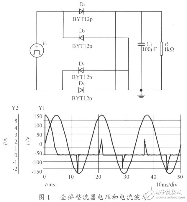
It can be seen that PF is determined by γ and cosφ. If the cosφ is low, it means that the reactive power of the electrical equipment is large, the utilization rate of the equipment is low, and the winding loss of the wires and transformers is large. If the γ value is low, it means that the input current harmonic component is large, causing pollution to the power grid. In severe cases, the three-phase four-wire power supply will also cause the neutral line potential to shift, causing damage to the electrical equipment. Since the conventional rectifying device uses a thyristor or a diode, the conduction angle of the rectifying device is much smaller than 180°, thereby generating a large amount of harmonic current components, and the harmonic current does not work, only the fundamental current works, and the power factor is low. The full-bridge rectifier voltage and current waveforms are shown in Figure 1.
2 power factor correction implementation method
It can be known from equation (1) that there are two ways to increase the power factor, even if the input voltage and the input current are in phase; the input current is sinusoidal.
Power factor correction technology can make the AC input current waveform completely track the AC input voltage waveform, make the input current waveform pure sine wave, and be in phase with the input voltage. At this time, the load of the rectifier can be equivalent to pure resistance.
Power factor correction circuits are classified into active and passive types. Passive correction circuits usually consist of large-capacity inductors and capacitors. Although the power factor of the passive power factor correction circuit is not as high as that of the active power factor correction circuit, the power factor can be increased to o. 7~0.8, so it is widely used in small and medium power supplies. Active power factor correction circuits have been rapidly popularized since the 1990s. It adds a power conversion circuit between the bridge rectifier and the output capacitor filter to bring the power factor close to one. The active power factor correction circuit operates in a high frequency switching state, is small in size, light in weight, and is more efficient than a passive power factor correction circuit. This article focuses on active power factor correction methods.
Solar Panel,Portable Big Power Bank,Lithium Batteries Power Station,Portable Battery Powered Generator
Guangzhou Fengjiu New Energy Technology Co.,Ltd , https://www.flashfishbattery.com