Build a flexible engine simulator with the LabVIEW FPGA Module
"Using the LabVIEW FPGA Module to program on the FPGA of the NI PXI-7831R reconfigurable I/O board not only allows our system performance to exceed specifications, but also saves 90% in hardware build costs." - Matthew Viele, NaTIonal Instruments
challenge:
Develop an engine simulator for the hardware-in-the-loop (HIL) test of the engine control module.
solution:
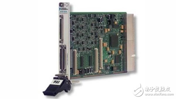
Use NI LabVIEW, the LabVIEW Real-TIme Module and the LabVIEW FPGA Module, and the PXI-7931R Reconfigurable I/O Board for real-time simulation and accurate, flexible timing and synchronization of I/O signals.
HIL Simulation Requirements As the world leader in industrial energy control technology, Woodward Industrial Controls works closely with engine and turbine OEMs to produce efficient control systems. Woodward's technology not only provides road speed load control, but also provides a variety of control systems that are widely used in emissions systems, generators, compressors, turbocharger control, and diesel/natural gas engines, gas/steam turbines, Ignition control of power generation systems, micro gas turbines and fuel cells. In order to test the new line of engine controllers, we need to build a system that simulates all input and output signals during engine operation.
Because the engine controllers we tested were able to continuously adjust the output related to ignition, fuel injection, and other engine performance, the test system must be able to continuously adjust in real-time closed-loop based on changes in engine parameters. These parameters include manifold pressure, air flow, engine speed, and engine temperature. The test system must also be able to detect engine knock, control turbocharger exhaust emissions, and achieve engine speed and torque set by the technician through the throttle.
Testing a engine control system with a real engine is a very dangerous and costly method. If the controller has a program error, it will cause problems such as knocking, overspeed, high temperature, damage to the test engine, and even lead to dangerous accidents in the test shop. Therefore, the real engine is generally only used for the final calibration work.
By simulating the engine output based on the controller input, we can get the controller's HIL test results without the engine. It also helps us simulate situations that are difficult to achieve when using a real engine in a test lab, such as operating under extreme conditions. In addition to simulating the normal operating environment, the test system simulates the fault condition by shorting and breaking the signal. Using a HIL simulator to test the controller, we can ensure that improvements to the control program for a new engine do not cause errors that were previously discovered when testing the engine with older programs. We don't need a real engine to test the new control method, and use the simulated data of the previously tested engine for regression testing.
Real-Time Simulation Engines Over the years, we have used a variety of engine controller test systems, including electric motor drives, complex programmable logic devices, and a complete turnkey system designed specifically for control units. Although these systems do meet some of our requirements, they are difficult to provide flexible, efficient and fully automated solutions, and we are having difficulty making further improvements to meet future testing needs.
For our latest engine controllers, we need to build our own system. Because we needed deterministic operations that only real-time operating systems could provide, we chose the LabVIEW Real-TIme module for simulation. In terms of I/O signals, we also used FPGA boards to meet our timing synchronization needs. In addition, in order to generate output waveforms and bursts, we need FPGAs to run much faster than the main emulation loop.
Before we knew about the NI LabVIEW FPGA Module and reconfigurable I/O hardware, we had carefully studied how to build our own FPGA-based hardware system. We also found a board that integrates the FPGA and integrated I/O ports. However, using the LabVIEW FPGA Module to perform FPGA programming on the NI PXI-7831R reconfigurable I/O board, not only does its performance parameters outperform our predetermined specifications, but it also saves 90% of the cost of developing hardware. Of course, some of the cost savings come from increased productivity. But with the LabVIEW FPGA Module, we can easily program in LabVIEW, eliminating the need to hire high-paying and scarce VHDL designers. Using LabVIEW 7 Express to configure the FPGA, our software developers can do it themselves without the help of a hardware engineer.
Signal synchronization and generation
In order to accurately represent the operating conditions of an engine, we must synchronize the various signals with the crank angle, which represents the operating position of the engine. To properly test a controller, we must also acquire the controller output, and the sampled signal is synchronized with the crankshaft signal generated by our system. Here, we used the analog output port on the PXI-7831R reconfigurable I/O board to simulate a variable reluctance crank sensor. We track the engine's operating position with a crank angle resolution. For example, if the engine is operating at 4000 rpm, the engine position tracking scan frequency is 24 kHz. By configuring the PXI-7831R's FPGA with the LabVIEW FPGA Module, we generated simulated signals such as crank angle, knock, and manifold pressure to synchronize with the controller's measurement signal, with a resolution of up to 25 nanoseconds.
When generating the simulated output signal, it is necessary to ensure that the output channel control of the I/O board is faster than the engine simulation main loop. Our LabVIEW Real-TIme simulation loop runs at 1KHz, which is the decision frequency. Once a decision is made, the system must quickly generate an input and output signal to execute the control command. For example, during testing, the engine controller may control the engine to operate in a knocking state. Models running in the LabVIEW Real-Time Module can produce a certain amount of knock for a particular cylinder control. The FPGA on the PXI-7831R board then generates this output signal. In addition, in the "knocking window" between the crank angle and the crank angle, the system must also output an output signal of the correct frequency and amplitude to the controller under test. In summary, with the LabVIEW FPGA Module and the PXI-7831R reconfigurable I/O board, we solved the problem of not being able to fully perform HIL simulation before.
We also generated other signals from the simulation system that did not need to be synchronized with the crank angle, including: switch, temperature, pedal position, throttle position, and vehicle speed. We generated these signals on other independent output channels of the PXI-7831R reconfigurable I/O board. Each analog input and output has a dedicated analog to digital or digital to analog converter. With the FPGA architecture, we can parallel multiple processes simultaneously. Although there is no operating system on the FPGA, it is like a chip with multiple, independent processors that can be custom designed for specific tasks.
Expanded NI Automotive Test Platform
The LabVIEW FPGA Module and reconfigurable I/O hardware have extended the NI automotive test platform to the engine test controller HIL simulation application. In real-time engine simulation, more and more I/O timing synchronization control, as well as fast decision making on the board's output signal, will become very important. Now, we have been able to build and improve a test system that meets all of the basic ECU testing needs.
Recommended configuration:
LabVIEW FPGA Module
PXI-7831R FPGA Module
Switching Current Transformer,Outdoor Switching Current Transformer,Busbar Built-In Current Transformer,Outdoor Split Core Current Transformer
Zibo Tongyue Electronics Co., Ltd , https://www.tongyueelectron.com