Design and Application of Radio Frequency RFID Shopping Guide Robot Navigation and Control System
This paper adopts the method of combining radio frequency identification technology, infrared distance sensing technology and geomagnetic induction electronic compass, and designs a navigation and control system for autonomous mobile robot based on information fusion controlled by DSP. In the design process, according to the actual needs, some improvements have been made to the traditional infrared obstacle avoidance sensors. At the same time, some research and discussion have been made on the purchase design of the driving system of the DSP system under the information fusion state. The design of the drive circuit for the motion control of a small robot is given. Finally, the robots designed by themselves under this architecture were tested in the supermarket for actual stability.
1 Introduction
With the development of science and technology and the improvement of people's living standards, robots have begun to enter people's lives. With the advent of this era, various new types of robots have emerged, such as cleaning robots and security robots. One of the most important parts of mobile robots: the navigation system has attracted more attention in the field of robots. Robot navigation systems are essential for many robot application areas such as: smart warehouses, supermarket shopping guides, home robots, automated libraries, smart hospitals, etc. The more common is the hunt robot. During the graduate study, the author has participated in such robot competitions and designs many times. In the actual design, it was found that because of the limitation of the fixed line, this system cannot achieve a full range of autonomous operation in the true sense. In addition, this method is greatly affected by light and cannot be practically used in life. Lines on the ground will also affect the appearance of the ground. After thorough literature search and thinking, a new robot navigation system is proposed, which integrates RFID, geomagnetic induction, DSP and other technologies. The actual system hardware and software design and stability tests were carried out.
2 Navigation hardware system
The hardware system we developed mainly consists of: DSP core board, RFID board, system motherboard, electronic compass, and driver board.
2.1 DSP core board
Our self-designed DSP system uses TMS320F2812 as the core. 2812 is a 32-bit fixed-point DSP chip with high performance, multi-function, and high cost performance for control by TI. The core uses a high-speed processor, mainly to consider the future secondary development of the system. And easy to transplant the algorithm. The instruction system can work at a maximum frequency of 150MHZ, with 18k of 0 wait period on-chip SRAM and 128k on-chip access time of 36ns FLASH. The on-chip peripherals mainly include ADC, dual SCI, SPI, McBSP, eCAN, etc., and with event management modules (EVA, EVB), including 6 PWM / CMP, 2 QEP, 3 CAP, 2 16-bit Timer. The dual SCI can connect the sensor all the way to the PC and output debugging information in time. 16-bit PWM can achieve fine speed regulation. CAP etc. facilitate the interface with the sensor. The maximum input is 16 channels, 12 bits of 3V, and the conversion time of 80ns ADC can be connected to 16 distance sensors at the same time. The 2812 has a 16 × 16-bit double multiplier accumulator, which can provide sufficient processing speed for processing RF and geomagnetic direction signals. Due to the particularity of the 2812 core voltage (1.8V) and start-up frequency, this core board uses a passive crystal oscillator.
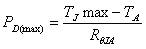
The core board adopts TPS767D318 dual output low-dropout LDO. Provide dual power supply to ensure a stable supply of core voltage 1.8V. TPS767D318 has a high-speed transient response, dedicated to DSP, and can provide a maximum current of 1A. Can realize the time-shared reset of IO and core. With power-on reset function and low-voltage protection function, the reset delay time is 200ms. With overheat protection function. The maximum power calculation can be calculated using Equation 1.
 (1)
(1)
Among them, TJMAX is the maximum allowable temperature, according to experience, the general TPS767D318 is about 125 degrees. TA is the ambient temperature. RθJA is the connection impedance. It is usually 27.9 ° C / W for 28 pins. The actual power consumption can be calculated by Equation 2, where VI and VO are the input and output voltages respectively, and IO is the output current.
 (2)
(2)
In terms of peripheral voltage filtering, a multi-stage tank capacitor (104 and 220uF) is used in parallel. Such a design can produce a low ESR effect. According to experience, in the frequency domain, 104 can greatly filter out high-frequency interference, and 220uF can optimally reduce the low-frequency interference of voltage.
2.2 System motherboard and sensor module
Regarding the power supply, the system uses a 12V lithium battery for power supply and a three-terminal positive voltage regulator to regulate the voltage. Internal integrated power protection. The output current can reach 1A. The input withstand voltage can reach 30V. Provides a charging interface, which is controlled by a switch, and an interface is left on the circuit board to charge the lithium battery.
The positioning device uses radio frequency technology (RFID). RFID has become a hot technology. Wal-Mart recently passed a "requires its top 100 suppliers to use RFID technology when sending pallets and crates to their distribution centers by January 2005, and gradually uses this technology in individual products after 2006." resolution. From the basic principle of information transmission, RFID technology is based on the transformer coupling model (energy transfer and signal transmission between the primary and secondary) in the low frequency band, and the space coupling model based on the radar detection target in the high frequency band (radar emits electromagnetic wave signals After encountering the target, carry the target information back to the radar receiver). The most basic RFID system consists of three parts: tags, readers, and antennas. According to the action distance, it can be divided into densely coupled cards (action distance less than 1 cm), near-coupling cards (action distance less than 15 cm), sparsely coupled cards (action distance about 1 meter) and long-distance cards (action distance from 1 meter to 10 Meters or even further). This system uses a near-coupling card. The radio frequency module communicates with the SCIA port of 2812. Determine the position of the robot by decoding the data stream.
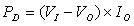
Next is the infrared obstacle avoidance module. The obstacle avoidance of general robots can use infrared reflection method, which is more common in robot competitions. GPIO controls the emission of infrared rays, and then reflects back if it encounters an obstacle. The receiving tube causes the resistance to change after receiving the light. Detecting the resistance change can determine whether there is an obstacle. But this method is susceptible to interference from optical noise. So the distance is relatively close, generally only reach 2-3cm. In many competitions, after checking materials and research, I proposed a circuit that uses standard high-frequency signal 38KHZ infrared to detect obstacles. Because of the use of high-frequency signals and high-frequency op amps, it has a certain anti-interference ability, and the maximum detection distance is increased to 8cm. First, infrared rays are emitted through 555. Then, the signal passes through the infrared receiving tube, passes through the DC blocking capacitor, and is sent to the high-frequency op amp LM318N, as shown in Figure 4. Then, after 50 times magnification. As shown in Figure 5 and Figure 6.
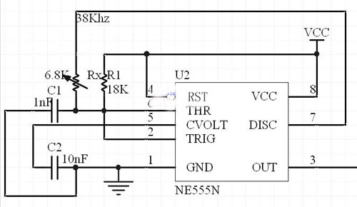
Figure 1 555 transmitting circuit
Figure 2 Frequency identification circuit
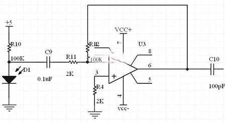
Figure 3 detection amplifier circuit
LM567 is a phase-locked loop circuit, 8-pin dual in-line package. The external resistance and capacitance of pins 5 and 6 determine the center frequency of the internal voltage controlled oscillator. Pins 1 and 2 are usually grounded through a capacitor to produce an output filter network and a loop single-stage low-pass filter network. The capacitance connected by pin 2 determines the capture bandwidth of the phase-locked loop: the larger the capacitance value, the narrower the loop bandwidth. The center frequency and filter bandwidth of the voltage-controlled oscillator can be determined by Equation 3 and Equation 4.
 (3)
(3)
 (4) (where Vi is the input voltage)
Then there is the electronic compass module. CMPS03 electronic compass is a plane angle sensor. By detecting the direct angle between the current sensor and the earth's magnetic field, the electronic compass can obtain an absolute rotation angle with a resolution of 0.1 degrees. This electronic compass module is specially manufactured for robots, the purpose is to provide the robot with appropriate direction navigation signals. For any direction, a unique code can be generated. The sensor uses PHILIPS KMZ51 geomagnetic induction chip, its accuracy is very high. There are two output modes, the first one: I2C mode, output by Pin2 (SCL) and Pin3 (SDA). Pin7 and Pin5 must be left floating. Pin6 is used for calibration. These pins are connected to the motherboard, because the module is 5V power supply, and the DSP is 3.3V, so you need to use 74LVC245 for level conversion. Correct the system through Pin6 through GPIOB of 2812. Calibration only needs to be done once, because the data will be saved in the EEPROM of the PIC microcontroller in the electronic compass. Pin 6 has a pull-up resistor. To perform calibration, you only need to give Pin6 a negative phase pulse through GPIO, and because of the pull-up resistor, it is also possible to disconnect this pin from the system.
Finally, the design of the drive module of the system. Using L298 chip. L298 is a product of SGS Company. The more common one is the L298N in 15-pin MulTIwatt package, which also contains a 4-channel logic drive circuit. The power output device contained in the L298 is designed and manufactured on a quartz substrate. Due to the uniformity of the manufacturing process, it has unmatched performance parameter consistency of discrete component combination circuits and stable operation. Pin 15 is the output current feedback pin, the other is the same as L293. In normal use, these two pins can also be directly connected to ground. It is a high voltage, high current dual full-bridge driver chip. Standard TTL logic levels can be directly accepted. Can drive various loads such as motors, relays, etc. There are two enable inputs, through which the effectiveness of the PWM wave is controlled. L298 integrates two energy output blocks A, B. In addition, we designed a freewheeling diode on the board.
2.3 Driver design
By writing InitSysCtrl () function, set the watchdog control register WDCR, its WDFLAG bit is the watchdog reset status bit. If this bit is set, it indicates a watchdog reset. Writing a 1 to the WDDIS bit invalidates the watchdog module. Write 0 to enable watchdog. The WDPS bit mainly determines the clock rate of the watchdog counter. Because the program contains many loops, pay special attention to the setting of the watchdog. Then set the PLL by setting the PLLCR. At this time, it should be noted that the program needs to be added, and 5000 cycles wait for the phase lock to stabilize. This is not necessary in 2407, but pay attention to this point for the 2812 system. Then use HISPCP and LOSPCP to match the high-speed and low-speed peripherals. Because the interrupt is used in the program, the peripheral interrupt extension PIE needs to be set. The direction sensor is connected to the DSP core through the capture unit. The capture of a pulse requires two interrupts, and the pulse code of the direction information is taken out by controlling and reading the FIFO register. In addition, the infrared obstacle avoidance module is connected to the interrupt pin after switching the level through the 74LV245 module. So we must program the interrupt function. Communication with RFID sensors is via 2812 two-wire asynchronous serial port. The SCI module supports digital communication between the CPU and asynchronous peripheral devices that use the non-return-to-zero (NRZ) standard format. The 2812's SCI receiver has a 16-level deep FIFO, which can reduce short service. The program determines whether there is an RFID interrupt by judging the TxRDY bit. In this way, it can be found in time whether the robot has reached a new position. Then read SCIRXBUF. Finally, the PWM pulse is set by the EV unit to control the direction of the robot.
3 Conclusion and system after implementation
Finally, debug the entire system near Lianhua Supermarket. After repeated debugging and modification of the program, the navigation of the RF path point was realized. The final system operation is shown in Figure 6:

Figure 4 The actual operation of the robot in the supermarket
27 Inch Aio,All In One Pc 27 Inch,All In One Desktop Touch Screen,All In One Pc Touch Screen
Guangzhou Bolei Electronic Technology Co., Ltd. , https://www.nzpal.com