Design of Active Filter Controller Based on DSP Processor
1 Introduction
The rapid development of power electronics technology has made various power electronic devices widely used in industry, transportation and home, and the harmonic hazards caused by these non-linear loads are also becoming more and more serious. Harmonics cause harmonic losses in components of the power grid, equipment efficiency and power factor reduction, and even damage to power equipment such as capacitors; harmonics affect precision instruments and adjacent communication systems, making them inoperable.
The number and magnitude of harmonics in the power system vary with system load conditions. Traditional LC static filters cannot meet the requirements. Power active filters can be used to dynamically change the harmonics and varying reactive powers that vary in size and frequency. Compensation, so the research and application of active filters has received more and more attention. The basic principle of the active filter is: firstly detect the harmonic current from the compensation object, and then the compensation device generates a compensation current with the same magnitude and opposite phase of the harmonic current, which cancel each other out and make only the grid current Contains the fundamental component. The controller is the core component of the active filter. It controls the behavior of the active filter by generating and controlling the pulses that drive the switching device, and performs dynamic compensation of harmonics and reactive functions.
2 Control system structure and basic functions
The main circuit of the active filter adopts a three-phase bridge type voltage type converter, which is coupled with the system through a transformer, and its structure is shown in FIG. The three-phase bridge structure is adopted because the control of the three single-phase bridges can be decoupled from each other, and can also be used to eliminate the zero-sequence component and its harmonic current, thereby achieving asymmetric control.
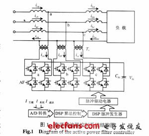
The active filter control system uses a dual DSP architecture, one DSP processor for data processing, control and high-level protection functions, and another DSP processor for generating high-precision PWM pulses. The controller mainly has the following functions:
(1) Controlling the behavior of the active filter
Controlling the output voltage of the inverter according to the detected harmonics of the load current and the reactive current component, so that the compensation current outputted by the active filter cancels the sum of the load harmonic current and the reactive current, thereby making the system current The fundamental wave positive sequence active current.
(2) Generate a trigger pulse
The driving circuit controls the turn-on and turn-off of the IGBT to generate a PWM trigger pulse, so that the active filter can output the correct harmonic compensation current.
(3) Pulse synchronization
Based on the synchronizing pulse retrieved from the grid, a pulse signal synchronized with the grid voltage is generated to synchronize the output of the active filter with the grid voltage.
(4) Self-fault tolerance
Once the controller itself has some components (such as voltage transformer (PT) disconnection, etc.), the controller can immediately find the error and alarm, and does not make the device out of operation, the fault can be easily restored after the fault is repaired.
(5) Protection function
When the active filter is operating in an overload or other abnormal state, and the current does not exceed the setting value of the protection action, the controller can return the active filter to the normal working state through the protection function, thereby avoiding the underlying protection action. This ensures that the active filter can work continuously.
3 Active filter controller implementation
The block diagram of the active filter controller is shown in Figure 2.
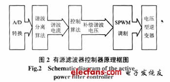
The controller samples and A/D converts the load current, the compensation current output by the device, and the system voltage at a sampling frequency of 60 & TImes; 50 Hz (or higher). The harmonic separation algorithm such as dq decomposition method or ab decomposition method and other methods are used to decompose the sampling current, filter out the active component of the fundamental wave, and retain the harmonic current required for compensation. Then use the control algorithm to calculate the harmonic voltage that the inverter should generate according to the circuit parameters. The instantaneous value of the harmonic voltage is sent to the DSP pulse generator, and the pulse generator uses the SPWM algorithm to determine the action of the inverter switching element according to the instantaneous value of the harmonic voltage. The pulse generator performs an SPWM pulse calculation based on the instantaneous value of the voltage to generate a drive pulse.
The functions of the controller are described below.
As a mobile multi-purpose platform, tablet computers also provide many possibilities for mobile teaching. The touch-based learning & entertainment teaching platform allows children to efficiently improve their academic performance in a relaxed and pleasant atmosphere. Such tablet computers generally integrate two learning sections of various courses and systematic learning functions. Generally, it includes multi-disciplinary high-quality teaching resources. The education tablet has the following main functions: it has the functions of touch screen input, text editing, picture editing, data storage, data management, wired and wireless Internet access that ordinary tablet computers have; Management functions, search methods support manual search, query by keyword, query by time; text and pictures can be scanned and converted into documents to save.
Education Tablet,learning tablet,leaning machine,New learning tablet
Jingjiang Gisen Technology Co.,Ltd , https://www.jsgisengroup.com