Design of Embedded Laser Tracker Based on DAC7714
The device driver occupies an extremely important position in the Linux kernel. In an embedded system, all device control operations must be completed by the driver except the CPU, memory, and other few components. The system designer must develop the appropriate driver for each peripheral in the system, otherwise the device cannot work properly under Linux.
In an embedded laser tracker based on the AT91RM9200 processor, in order to achieve a fast and stable tracking of the target, it is necessary to control two motors, ie, azimuth motor and pitch motor. The principle is as follows: By continuously reading the data of two-way angle encoders, the deviation between the actual angle and the desired angle of the two-way motor is calculated, and the principle of feedback control is used to drive the two-motor tracking target. When the control voltage of the two-way motor is 5V, the motor stops; when the control voltage is 0V, the motor rotates clockwise at the maximum speed; when the control voltage is 10V, the motor rotates counterclockwise at the maximum speed.
According to the above control requirements, a 4-channel 12-bit serial DA converter, the DAC7714 converter, is selected as the control driving chip of the two-way motor. The advantages and disadvantages of this chip in the embedded Linux system will directly determine the tracking effect of the entire instrument, and it is also one of the basic problems that need to be solved in embedded development.
1 Overview
The DAC7714 is a 4-channel 12-bit serial input, voltage output DA converter introduced by TI of the United States. The power supply voltage is ±15 V, and the output can be automatically maintained. In addition to the advantage of saving microcontroller resources, this serial port chip also has multiple outputs of 0 to 10 V at the same time (reference voltage is +10 V and 0 V). Applicable to MCU resources shortage and control channel more occasions.
DAC7714 performance characteristics:
1) 12-bit resolution, serial interface;
2) The power consumption is only 250 mW;
3) 4 analog output channels, voltage output;
4) linear error ± 1LSB;
5) support unipolar (0 ~ 10 V) or bipolar (-10 V ~ +10 V) output;
6) Automatic output retention;
7) Reset signal is optional, different reset methods have different initial values.
2 Hardware Design
The hardware of embedded laser tracker is more complicated. Here we introduce the hardware connection part of DAC7714 and AT91RM9200 related to motor drive. Due to the fact that the motor power during actual use is large, it is necessary to add a primary drive circuit to the two outputs of the DAC7714 to actually drive the motor.
2.1 DAC7714 Pins and Functions
DAC7714 is SOJ16 package, the specific pin and function are introduced as follows:
VOUTA~VOUTD: 4 analog outputs
CS: chip select, active low
CLK: serial data clock
VCC: Positive Supply, Usually +15 V
VSS: Negative Supply, Usually 0 or -15 V
GND: Ground
VREFL: Analog Output Voltage Reference (Lower Limit)
VREFH: Analog Output Voltage Reference (upper limit)
SDI: Serial Data Input
LOADDACS: Conversion End Judgment Bit
RESET and RESETSEL: Chip Reset Setting Bits
2.2 DAC7714 Hardware Design
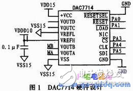
DAC7714 hardware design is relatively simple, and its programmable pins RESET, LOADDACS, CS, CLK, SDI and AT91RM9200 IO port PA0-PA1, PA3-PA5 connection, lay the foundation for the next driver development; its VOUTA, VOUTB then two Road motor control signal; VREFL grounded, VREFH connected +10 V, using unipolar connection. The specific connection is shown in Figure 1.
Mobile Led Display,Led Screen Mobile,Led Screen For Mobile,Led Display In Mobile
ShenZhen Megagem Tech Co.,Ltd , https://www.megleddisplay.com