Ds1991 features, working principle plus password protected memory area read and write
Dallas's iButton product is a series of new 1-Wire bus devices. DS1991 is a kind of encrypted memory type information button. It is enclosed in a stainless steel shell with a diameter of 16mm. It is small in size, easy to carry, save, dustproof, and corrosion-proof. It can realize password protected data transmission in harsh application environment. This article introduces the DS1991's features, working principles, and read and write methods with password protected memory areas.
Features of 1DS1991DS1991 is a very special kind of encrypted memory type TM card, which is a reliable protection measure for the user's confidential data price increase section. The DS1991 has a 1152-bit password protected memory area and a 512-bit non-password protected memory scratchpad. The password-protected memory is divided into three independently operable key sub-memory (subkey), each of which is 384 bits. Each cash money sub-area has its own 64-bit password and 64-bit ID code. Read/write operations in the zone require password verification. The data in the three districts can be operated separately without disturbing each other. The non-password protected memory area is mainly used for encrypting the data copy to ensure the integrity of the data.
2 DS1991 and MCU hardware interface and software designDS1991 and the microcontroller's hardware interface circuit shown in Figure 1.
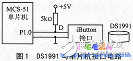
DS1991 interface with the microcontroller is very convenient, only with a data line and an address. Data line by the microcontroller 1 I / O port line control, port line external 5kΩ pull-up resistor. DIOBITP1.0; pin definition RETDJNZR6, WRB1
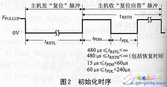
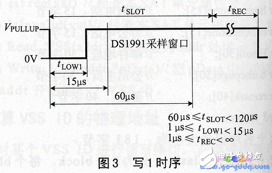
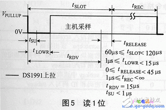
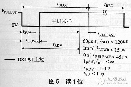
DS1991 operation is based on the 1-wire bus initialization, read / write 1-bit timing, as shown in Figure 2, Figure 3, Figure 4, and Figure 5. VPULLUP is the point D in Figure 1 when the port is in the input state of the potential. Initialization Reset pulse sent by the host. DS1991 reply to the response pulse, so that the host knows that the DS1991 exists on the bus and is ready for operation. Each byte of the command and data is transmitted one bit from the least significant bit. Subroutine RESET, RDBYTE and WRBYTE is a subroutine that initializes, reads/writes 1 byte, respectively.
RESET:CLR DIO; subroutine
MOV R7, #205
DELPP1:NOP
DJNZ R7, DELPP1
SETB DIO
MOV R7, #12
DJNZ R7, $
MOV R7, #27
RESETP1:JNB DIO,RESETP2
DJNZ R7, RESETP1
RESRET:SETB DIO
MOV A, #0EH
RESETP2: MOV R7, #75
DJNZ R7, $
MOV R7, #54
RESETP4:JB DIO,RESETP5
DJNZ R7, RESETP4
RESETP5:MOV R7,#180
DJNZ R7, $
SETB DIO
MOV A, #0
RET
WRBYTE: MOV R6, #8; Write 1 byte subroutine
WRB1: CLR DIO
MOV R7, #2
DJNZ R7, $
RRC A
MOV DIO,C
MOV R7, #30H
DJNZ R7, $
SETB DIO
NOP
NAP
NOP
RET
RDBYTE:MOV R6,#8 ; Read 1 byte subroutine
RDB1: CLR DUO
NOP
NOP
SETB DIO
MOV R7, #3
DJNZ R7, $
MOV C, DIO
RRC A
MOV R7, #32
DJNZ R7, $
SETB DIO
MOV R7, #3
DJNZ R7, $
DJNZ R6, RDB1
RET
Like all 1-Wire bus devices, the host must perform initialization and ROM operations before it can read and write DS1991 memory operations.
DS1991 has its own unique factory-introduced 64-bit laser ROM series code. This code will not be compared with any other 1-wire bus device. The first 8 bits of the code are 1-wire bus family code, and the last 48 bits are The only serial number of the device, the last 8 bits are the CRC of the first 56 bits. The ROM operation instruction establishes the connection between the accessed 1-wire device and the host. The ROM operation instruction is shown in Table 1. .
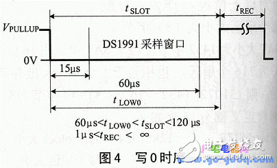
Table 1 ROM operation instructions
MOV A, #0
RET
WRBYTE: MOV R6, #8; Write 1 byte subroutine
WRB1: CLR DIO
MOV R7, #2
DJNZ R7, $
RRC A
MOV DIO,C
MOV R7, #30H
DJNZ R7, $
SETB DIO
NOP
NAP
NOP
RET
RDBYTE:MOV R6,#8 ; Read 1 byte subroutine
RDB1: CLR DUO
NOP
NOP
SETB DIO
MOV R7, #3
DJNZ R7, $
MOV C, DIO
RRC A
MOV R7, #32
DJNZ R7, $
SETB DIO
MOV R7, #3
DJNZ R7, $
DJNZ R6, RDB1
RET
Like all 1-wire bus devices, the host must perform initialization and ROM operations before it can read and write DS1991 memories.
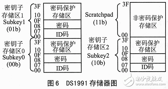
The DS1991 has its own unique factory-introduced 64-bit laser ROM series code. This code will not be the same as any other 1-wire bus device. The first 8 bits of the code are the 1-wire bus family code, the last 48 bits are the only series code of the device, and the last 8 bits are the CRC of the first 56 bits of data. The ROM operation instruction establishes a connection between the accessed 1-wire device and the host. The ROM operation instruction is shown in Table 1. The DS1991 memory map is shown in Figure 1.
Table 1 ROM operation instructions
Command word function
Read ROM 33H reads the ROM code of the DS1991
Match ROM 55H Bus Used to Address Specific Devices When Connected to Multiple Devices
When there is only one device on the Skip ROM CCH bus, memory access is skipped by skipping ROM series code matching
Search ROM F0H host uses this command to read and add the device ROM series code
The DS1991's scratchpad and each subkey area have their own address. The Scratchpad is 64 bytes in total and is not password protected. It is mainly used to copy data to the key subsection. 00~07H in the key subarea are 8-byte ID codes in this area, 08H to 0FH are 8-byte passwords in the area, and 10H to 3FH are password-protected data storage areas.
The/Scratchpad does not require a password, but the copy operation must provide the correct password. The read and write of the codon area is protected by a 64-bit password, and the confidentiality is greatly improved. The operating instructions for memory are shown in Table 2. The memory operation instruction flow is shown in Figure 2.
Table 2 DS1991 memory operation command format
Command 1st byte 2nd byte 3rd
byte
Features
Bit7 bit6 bit5 bit4 bit3 bit2 bit1 bit0
Write any value in scratchpad 96H 1 1 00H to 3FH 2nd byte negated Write data to scratchpad
Read scratchpad 69H read data from scratchpa
Copy scratchpad 3CH Subke Area Code
0 0 or
0 1 or
1 0 0 0 0 0 0 0 Copy the data block from scratchpa to the specified subkey
Read any value in subkey 66H 10H to 3FH Write data to subkey
Write subkey 99g to read data from subkey
Write Password 5AH 0 0 0 0 0 0 Write password and ID code to subkey
4 DS1991 memory read and write procedures
Host read and write DS1991 memory consists of three steps: initialization, ROM operation and memory read and write.
The following program uses the write SUBYKEY command to write the RAM 40H to 47H cell data to 10H to 17H in the subkey 0 area, and read the contents back with the read SUBKEY command to store the RAM. 50H to 57H, the password and ID code in this area are stored in the program's table.
Write RAM40H to 47H cell contents
;subkey
WRSUBKEY: LCALL RETSET
MOV R2, #99H
MOV R0, #10H
LCALL WRCOM
LCALL IDPASS
MOV R1, #40H
MOV R4, #8
REWRSUB: MOV A, @R1
LCALL WRBYTE
INC R1
DJNZ R4, REWRSUB
LCALL RESET
RET
; Read subkey into RAM40H ~ 47H
RDSUBKEY: LCALL RESET
MOV R2, #66H
MOV R0, #10H
LCALL WRCOM
LCALL IDPASS
MOV R1, #40H
MOV R4, #8
RERDSUB: LCALL RDYBTE
MOV @R1,A
INC R1
DJNZ R4, RERDSUB
LCALL RESET
RET
IDPASS: MOV R4, #8
MOV R1, #50H
RERD1: LCALL RDBYTE
MOV @R1,A
INC R1
DJNZ R4, RERD1
MOV R4, #8
CLR A
MOV DPTR, #PSTAB
REWR1: MOVC A, @A+DPTR
LCALL WRBYTE
INC A
DJNZ R4, REWR1
RET
IDTAB: DB10H, 00H, 00H, 00H,
DB 00H, 00H, 00H, 00H
PSTAB: DB12H, 34H, 56H, 78H, DB12H, 34H, 56H, 78H
WRCOM: MOV A, #33H
LCALL WRBYTE
MOV R4, #8
RDROM1: LCALL RDBYTE
DJNZ R4, RDROM1
MOV A, R2
LCALL WRBYTE
MOV A,R0
LCALL WRBYTE
MOV A,R0
CPL A
LCALL WRBYTE
RET
ConclusionDS1991's password protected memory area provides users with highly reliable data protection measures. The software and hardware design of DS1991 and SCM interface provided in this paper has been applied in the information button type utility meter system.
Variable Frequency Transformer
Variable Frequency Transformer,Voltage Variable Frequency,High Voltage Variable Frequency,Dry Type Transformer
SANON DOTRANSÂ Co., Ltd. , https://www.sntctransformer.com