Hands-on class: Analog mixed signal on Zynq SoC
Using XADC inside the Zynq SoC can greatly increase system integration and is very simple and intuitive to implement.
The Xilinx Zynq®-7000 All Programmable SoC comes complete with an XADC module with two 12-bit analog-to-digital converters (ADCs). The two ADCs have a sampling rate of up to one million samples per second (1MSPS) with an ideal 500kHz effective input signal bandwidth (the auxiliary input has a signal bandwidth of 250kHz). The XADC multiplexes 17 input signals and measures a range of internal voltages and temperatures. If your design does not provide enough analog input pins for external signals, the XADC should be configured to drive the external analog multiplexer and order all inputs in the required order.
The XADC is capable of unipolar or bipolar measurements, so the input to the device is a differential input. The 17 differential inputs are divided into a dedicated pair (called VP/VN) and 16 auxiliary inputs (which can be analog or digital I/O, called VAUXP and VAUXN). The effective input signal bandwidth depends on the type of differential input used. If a dedicated pair is used, the signal bandwidth is 500 kHz, and if an auxiliary input is used, the signal bandwidth is 250 kHz.
The XADC's mixed-signal performance is very good, with a minimum signal-to-noise ratio (SNR) of 60dB and a total harmonic distortion (THD) of 70dB, according to the data sheet. Depending on the temperature range of the device (-55oC to 125oC or -40oC to 100oC), the resolution of the XADC can be 10 or 12 bits. Thus, the effective number of XADCs calculated according to the following equation is 9.67.
ENOB = (SNR–1.76/6.02)
The XADC has an average of 16, 64 and 256 samples that can be selected by the user to reduce input noise. The user can also set maximum and minimum alarm levels for each measured internal device parameter.
What applications is XADCXADC suitable for?
Designers can use this ADC for a range of applications ranging from simple onboard parameters (voltage, current, and temperature) to telemetry, to support for touch sensors, motor control, or simple wireless communication protocols. In addition, it can be used in military or other important systems to detect device tampering.
One of the key advantages of XADC is to monitor a range of system internal parameters and verify the design's goodness. In addition, to simplify the initial verification of the design, you can use the XADC in a Zynq-7000 All Programmable SoC-based system to measure the temperature recorded by the on-chip temperature sensor and other subsequent parameters.
Hardware Implementation To use XADC, you first need to open the PlanAheadTM project that includes the Zynq SoC implementation (if you don't know how to do this, please refer to the cover article in the 47th issue of Xilinx China Newsletter). Select the processor subsystem you created and double-click to open Xilinx Platform Studio (XPS). You can modify the processing system in XPS.
Once XPS is open, select the IP Catalog tab on the left side of the project window and select AXI XADC under the Simulation menu. A prompt will appear asking if you want to add an IP to your design. Click Yes to display the IP configuration window, as shown in Figure 1. There isn't much to configure here, unless you want to optimize the complex AXI bus interface.
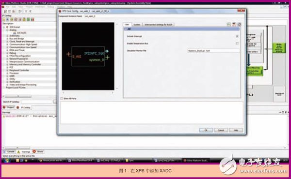
The user tag is the main control area. You can use this tag to add an interrupt to the processor to enable the temperature bus. You can connect the enabled temperature bus to the Memory Interface Generator to provide temperature information that affects timing. The simulation monitor file is used when simulating the XADC in ISim.
If you are satisfied with the XADC configuration, you can close the IP configuration window and the XADC will be added to the processing system. If you click on the address label of the System Assembly viewer, you will see the range of addresses assigned to the XADC and then tick to lock the address range.
The next step is to set the number of external ports connected to the XADC. By default, the XADC can support 1 external multiplexer, 16 auxiliary analog inputs, 8 alarm outputs, and 1 conversion start, as shown in Figure 2.
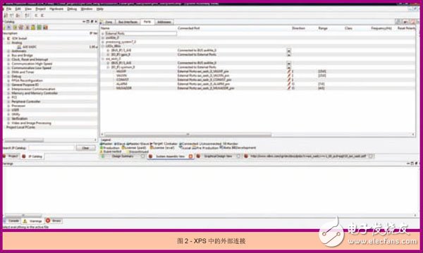
You can remove these ports if necessary, leaving only the dedicated analog inputs Vp and Vn for the ADC and the internal channel to the monitor. For example, ZedBoard can only support two auxiliary analog inputs on channels 0 and 8, as well as four XADC-specific GPIOs. You can connect these GPIOs to the alarm output or multiplexer output as needed. The external I/O can be disconnected by selecting the "Do not connect to external port" option in the drop-down menu in XPS.
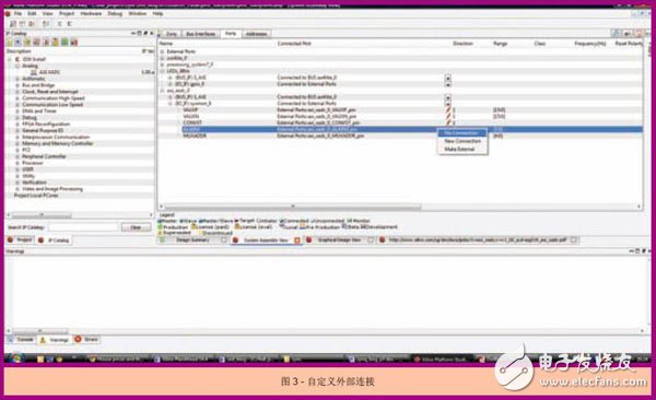
If you want to make some auxiliary inputs still connected (for example, adding two ZedBoard inputs), you can keep the VAUXP and VAUXN channels inside the system, while only channel 0 and channel 8 are connected at the top level of the RTL design. If you want to connect auxiliary input but remove other external ports, you need to right-click on a specific I/O and select the "No Connection" option, as shown in Figure 3.
After the external connection is set up, run the Design Rule Check (DRC). If the DRC does not show any errors, it can exit XPS and return to PlanAhead, where it generates a bitstream. If you look at the combined results, you'll see that the ADC is already in the resource list.
Writing the software hardware design is complete, you need to import the hardware into the software development kit (SDK) again in order to upgrade the board support package. Select File -> Export -> Export Hardware to SDK option in PlanAhead. A prompt will appear warning that we will overwrite the existing hardware definition. Click "Yes" and overwrite.
If the SDK is open, you will receive a prompt to describe the changes to the hardware specification file. If the SDK is not open, you will receive this prompt the next time you open it.
Click on the "Yes" option in the SDK prompt, the hardware definition will be updated and your project will be rebuilt. Assuming there are no errors in the design, you will begin to perform code modification work.
Open the system.xml or xparameters.h file and you will not only see the address range of all other peripherals in the design, but also the address range of the XADC that was just added to the XPS.
Opening the system.mss file will show the overall details of the board support package (BSP). What we are really interested in here is the peripheral driver, here you can see xai_adc_0 (or whatever you name the XADC in XPS). Next, you'll see a hot link to open the document and instance.
To reduce development time, Xilinx provides a series of drivers in the header file that make it easy for us to use these devices. You need to access these drivers in your code. To do this, you need to add the following header files generated during the BSP update process.
#include "xadcps.h"
This file contains definitions for the XADC registers, sample averaging options, channel order options, and power save modes. It also contains a list of type definitions, macros, and functions that can be used in the system.
Put together a simple example: I will read the system's internal temperature and voltage parameters and output them via the RS232 link.
The first thing to do when writing code is to query the configuration of the XADC that will be initialized. Here you will use the pointer of type XAdcPs_Config. The configuration information (device ID and base address of the XADC) is stored in the pointer using the XAdcPs_LookupConfig() function call and the device ID obtained from the updated xparameters.h file. The next step in the initialization process is to use the information previously acquired and stored in the configuration pointer, which requires a pointer of type XAdcPs.
Status_ADC = XAdcPs_CfgIniTIalize (XADCInstPtr, ConfigPtr, ConfigPtr->BaseAddress)
I named the configuration pointer ConfigPtr and named the instantiation pointer XADCInstPtr. After the initialization of the XADC is completed, configure it according to the requirements of the instance. The following is the configuration process:
1. Run the self test with the XAdcPs_SelfTest() function to verify that the device is ok.
2. Use the XAdcPs_SetSequencerMode() function to set the sequencer to a single channel to stop the current operation of the sequencer.
3. Use the XAdcPs_SetAlarmEnables() function to disable all alarms.
4. Use the XAdcPs_SetSeqInputMode() function to restart the sequencer and have it sorted in the order I want.
5. Use the XAdcPs_SetSeqChEnables() function to configure the channel so that it can be sampled according to my requirements.
After completing the above steps, you can use the ADC and receive data from the XADC. Simply call the XAdcPs_GetAdcData() function to read the samples from the XADC. For the internal temperature and voltage parameters, then I use the two provided macro commands (XAdcPs_Original ToTemperature() and XAdcPs_Original ToVoltage()) to convert the original XADC value to the actual temperature or voltage value.
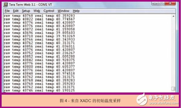
The actual value and the raw data are then output via the RS232 link. Figure 4 shows the initial results of sampling only the device temperature.
When I expand the sampling range to the internal power rail and temperature, I return the following results:
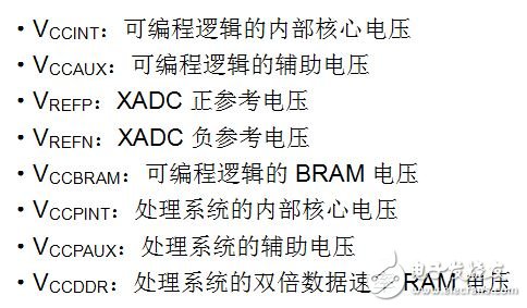
• Original temperature 40696, actual temperature 39.805603
• Original VccInt 21677, actual VccInt 0.992294
• Original VccAux 39431, actual VccAux 1.805008
• Original VccBram 21691, actual VccBram 0.992935
• Original VccPInt 21649, actual VccPInt 0.991013
• Original VccPAux 39402, actual VccPAux 1.803680
• Original VccDDR 32014, actual VccDDR 1.465485
All of these parameters are within acceptable limits for Zynq SoC operation, but require Zynq SoC to operate under laboratory conditions.
As you can see, implementing and using analog mixed signals in the Zynq SoC is straightforward and straightforward. XADC improves the integration and functionality of the All Programmable system.
Insulation Tubes,Pvc Pipe Insulation,Insulated Pex Pipe,Rubber Insulation Tube
Shenzhen Huiyunhai Tech.Co., Ltd. , https://www.cablesleevefactory.com