How to build your own CAN-bus application layer protocol
With the decline of the price of CAN-bus related chips and the increase of MCUs with built-in CAN controllers, CAN-bus has entered many fields that could not be used due to cost problems in the early days. It has become a very lively field bus. Today we will discuss how to Build your own CAN-bus application layer protocol.
On the CAN-bus network, the CAN message is sent in the form of a broadcast. The CAN message does not contain the address information. Whether to process the received CAN message is determined by the software of the receiving point. CAN-bus only provides reliable message transmission services. The use of CAN messages is defined by the application. Therefore, nodes in the CAN network must establish a unified rule to communicate with each other. The CAN application layer protocol is such a rule.
This rule defines the frame ID and frame data usage in the CAN message, such as defining the frame ID as the CAN node address that needs to process the frame data. Depending on the application, a variety of CAN application layer protocols have emerged internationally. The common CAN-bus application layer protocols are as follows:
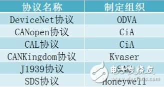
figure 1
Next, let's take a look at how to build a CAN-bus application layer protocol.· To build a fieldbus network, the key technical issues that need to be addressed are:
· Speed, capacity, priority level, node capacity, etc. of the bus transmission information;
· Reliable data transmission in high electromagnetic interference environments;
· Determination of the delay size at the maximum transmission distance;
· Network fault tolerance technology;
· Network monitoring and troubleshooting capabilities.
To solve the above problems, it is necessary to fully consider the type of bus used in the fieldbus network. Because the above problems are closely related to the performance characteristics of the bus, then we will look at the above characteristics of the CAN-bus bus:
· The CAN-bus network has a transmission speed of up to 1 Mbps and uses lossless arbitration to indicate the priority of the message through the message identifier.
· CAN-bus uses differential signal transmission and uses reliable data check and error detection mechanism;
· CAN-bus uses frame transmission, each message allows transmission of up to 8 bytes, the frame structure is strictly specified, and the maximum transmission delay can be determined;
· CAN-bus has a reliable error mechanism and detection mechanism. After the transmitted information is destroyed, it can be resent. If the node is in serious error, it has the function of automatically exiting the bus.
· Network monitoring and diagnostics can be solved by developing a forbidden CAN-bus application layer protocol.
CAN message distributionIt includes the assignment of message identifiers and the allocation of message data. The definition of the message format is essentially a detailed description of the assignment rules of CAN messages.
Definition of the message ID:
CAN2.0A frame: 11-bit ID
CAN2.0B frame, 29-bit ID
Definition of message data: Each frame message contains up to 8 bytes of data.
Implementation of CAN network data communicationIn the CAN network, the information is distinguished by the identifier of the message, so the purpose of establishing the information link is achieved by the various identifier assignments of the message.
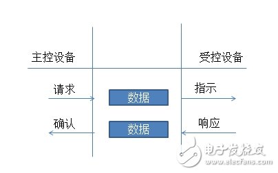
Figure 2 Command/Response Mode Communication
CAN application layer protocol: node-oriented and message-oriented protocolData communication protocols can be basically divided into two types: "node-oriented protocol" and "message-oriented protocol", as shown below:
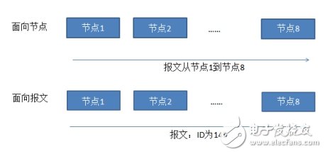
Figure 3: Node-oriented and message-oriented data communication
Develop a CAN application layer protocolIn order to demonstrate to the reader the development and use of the CAN application layer protocol, a simple CAN application protocol stack is defined below, in which only data frames in the CAN standard frame are used, and 11 bits in the frame ID are allocated and used. The method is listed in the following table. The protocol also defines the function parameter array FunData of the function parameter length variable FunDataLen, which can provide sufficient control parameters for some specific function functions when needed.
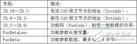
Figure 4
Degrees Of Freedom Platform,Wave Simulation Platform,Shipboard Motion Simulation Bench,flight sim motion platform
Suzhou Johnson Automation Technology Co., Ltd. , https://www.cn-johnson.com