How to draw the electrical schematic diagram?
Commonly used electrical diagrams include: electrical schematic diagrams, electrical component layout diagrams, and electrical installation wiring diagrams. The drawing size of various drawings generally chooses 297×210, 297×420, 297×630, 297×840mm, and four formats. For special needs, other sizes can be selected according to the national standard of GB126-74 "Mechanical Drawing".
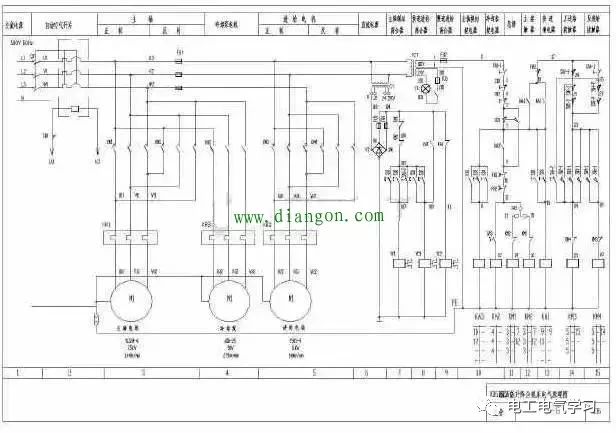
Electrical schematic diagram: The diagram that uses graphic symbols, text symbols, item codes, etc., to indicate the relationship and working principle of the various electrical components of the circuit is called the electrical schematic diagram. The electrical schematic diagram has a simple structure and a clear hierarchy. It is suitable for studying and analyzing the working principle of the circuit, and can provide help for finding faults. It is also the basis for compiling electrical installation wiring diagrams, so it is widely used in design departments and production sites.
The electrical schematic diagram is to draw the various parts of an electrical component in a separate form. There are also circuit diagrams drawn on the site in which the various components on the same electrical appliance are grouped together and drawn according to their actual positions.
The drawing method of the structure drawing is easier to identify the electrical appliances, which is convenient for installation and maintenance. However, when the wiring is more complicated and there are more electrical appliances used, the wiring is not easy to see clearly. Although the various parts of the same electrical appliance are mechanically connected, they are not necessarily related to each other in the circuit.
Drawing principles: 1. The electrical components in the electrical schematic diagram are drawn in the state when they are not energized and not subjected to external forces. In different working stages, the actions of various electrical appliances are different, and the contacts are closed and open. Only one situation can be shown in the electrical schematic diagram. Therefore, it is stipulated that the contacts of all electrical appliances indicate the position in the original situation, that is, the position when there is no electricity or no mechanical action occurs. For the contactor, it is the position when the coil is not energized and the contact is not operating; for the button, it is the position of the contact when the finger is not pressed; for the thermal relay, it is the normally closed contact when the The position during the overload action and so on.
2. The drawing position of the contact. The direction of the external force that causes the contact to act must be: when the figure is placed vertically, it is from left to right, that is, the contact on the left side of the vertical line is a normally open contact, and the contact on the right side of the vertical line is a normally closed contact; When placed horizontally, it is from bottom to top, that is, the contacts below the horizontal line are normally open contacts, and the contacts above the horizontal line are normally closed contacts.
3. The main circuit, control circuit and auxiliary circuit should be drawn separately. The main circuit is the drive circuit of the device, which is the path through which the large current passes from the power supply to the motor; the control circuit is a logic circuit composed of contactors, relay coils, and contacts of various electrical appliances to achieve the required control functions; auxiliary circuits include Signal, lighting, and protection circuits.
4. The power circuit of the power circuit is drawn as a horizontal line, and the power device (motor) receiving electricity and its protective electrical branch should be perpendicular to the power circuit.
5. The main circuit is drawn with a vertical line on the left side of the figure, the control circuit is drawn with a vertical line on the right side of the figure, and the energy-consuming components in the control circuit are drawn at the bottom of the circuit.
6. The figure shows the order of operations from left to right or top to bottom, and minimize lines and avoid lines crossing.
7. The connection points of the cross wires that have direct electrical connection in the figure (ie, the intersection of wires) should be indicated by black dots. For cross wires without direct electrical connection, black dots cannot be drawn at the intersection.
8. At the top of the schematic diagram, divide the diagram into several diagram areas, and indicate the purpose and function of the circuit in this area; below the relay and contactor coil, there is a contact table listed to illustrate the subordination of the coil and the contact.
Component layout drawing: The layout drawing of electrical components mainly shows the actual location of all electrical components on the electrical equipment, and provides necessary information for the installation and maintenance of the electrical equipment. The layout of electrical components can be drawn collectively or separately according to the complexity of the electrical equipment.
The figure does not need to mark the size, but the code of each electrical appliance should be the same as the code of all the components on the relevant drawings and electrical list. In the figure, more than 10% of the spare area and the location of the conduit (slot) are often left for improvement. Used in design.
Drawing principles: 1. When drawing the layout of electrical components, the contour line of the machine tool is represented by a thin solid line or a dot-dash line, and the electrical components are all drawn with a thick solid line to draw a simple outline.
2. When drawing the layout of electrical components, the motor and the mechanical device to be dragged should be drawn together; the limit switch should be drawn where the information is obtained; the operating handle should be drawn where it is easy to operate.
3. When drawing the layout of electrical components, keep a certain distance between the top, bottom, left, and right of each electrical component, and consider the heat and heat dissipation factors of the components, and it should be convenient for wiring, wiring and maintenance.
Installation wiring diagram: electrical installation wiring diagram is mainly used for the installation and wiring of electrical equipment, circuit inspection, circuit maintenance and troubleshooting. In the figure, the actual wiring between electrical equipment and electrical components should be shown, and the data required for external wiring should be marked. In the electrical installation wiring diagram, the text symbols, component connection sequence, and wiring number of each electrical component must be consistent with the electrical schematic diagram.
Drawing principles: 1. When drawing electrical installation wiring diagrams, all electrical components are drawn according to their actual positions in the installation bottom plate. The drawing area occupied by the components is based on the actual size of the meeting site in a uniform proportion.
2. When drawing electrical installation wiring diagrams, all parts of a component are drawn together and framed with a dot-dash line. Sometimes multiple electrical components are framed with a dot-dash line to indicate that they are installed on the same mounting base.
3. When drawing the electrical installation wiring diagram, the wiring between the electrical components inside and outside the installation base plate is connected through the terminal board. There are several leads connected to the external circuit on the installation base board, and several lines should be drawn on the terminal board. Of contacts.
4. When drawing electrical installation wiring diagrams, adjacent wires with the same direction can be drawn as a strand.
Secondary circuit diagram: (1) DC circuit from positive to negative: such as control circuit, signal circuit, etc. Start with the DC positive pole of a loop and follow the direction of current flow until you see the negative pole.
(2) AC circuit from live wire to neutral wire: such as current, voltage circuit, air-cooled circuit of transformer. Starting from the live wire (A, B, and C phases) of a loop, follow the direction of current flow until you see the neutral wire (N pole).
(3) See the contact to find the coil, see the coil to find the contact: See the contact to find the coil position of the relay or contactor that controls the contact. The loop where the coil is located is the control loop of the contact to analyze the conditions of the contact's action. See the coil to find all its contacts in order to find all the contacts (objects) controlled by the relay.
(4) Use Ohm's law to analyze the relay to determine whether it is operating: the basis of the judgment is that a large enough voltage is applied to both ends of the voltage-type coil, and a large enough current is applied to both ends of the current-type coil. For the coil circuit of a voltage type relay, when the two ends of the coil are connected to the positive and negative poles of the respective power supply through the contacts of several relays or the current coil, the relay (contactor) is considered to act (excite). When there is a short-open circuit in the circuit When the contact, or the coil circuit is connected in series with a relatively large resistance, or the coil is short-circuited by the parallel connection, the relay (contactor) is considered to be inoperative (not excited).
For example: a switch opening circuit, when the switch is in the closed position and a closing relay (large resistance) is connected in series to the positive end of the opening coil, it is considered to be inactive. When the protection trip contact is closed and the coil is directly connected to the positive pole of the power supply, it is considered that the opening coil has acted. For the current type (such as the anti-jumping relay of the trip circuit), when the two ends of the coil pass through the contacts of several relays or the coils with smaller resistance are connected with the positive and negative poles of the respective power supply, the relay (contactor) is considered to act (excitation) . When there is a short open contact in the circuit, or the coil circuit is connected in series with a relatively large resistance, or the coil is short-circuited by the parallel connection, the relay (contactor) is considered to be inoperative (not excited).
(5) Read all branches: When looking at a circuit from the positive pole to the negative pole, if there are multiple branches connected to the negative pole in the middle, then each branch must be read. Otherwise, some important situations will be missed in the analysis loop.
(6) Use relative numbering and circuit numbers to clarify the correspondence between the installation diagram and the equipment in the wiring schematic diagram of the expansion diagram: the main purpose of checking the correspondence between the installation diagram and the expansion diagram: the first is to check whether the installation diagram is the same as the expansion diagram Corresponding. Second, figure out the location of each device in the unfolded diagram. Check the position of the terminal of a Terminal Block in the expansion diagram from the installation diagram (such as the wiring diagram of the protective screen terminal block), first find out the circuit label where the terminal is located, and then check the circuit label in the expansion diagram, the same The circuit label is the same circuit, you can quickly find the circuit in the expansion diagram, and find out its role in the entire circuit in the expansion diagram.
If there is only the installation drawing on hand or the principle wiring diagram of the installation drawing cannot correspond to the expanded drawing, then from the number marked on each device terminal in the installation drawing, according to the relative numbering method, find out the connection of the other device Terminal, and then find out the other equipment connected to the terminal until the positive and negative poles of the DC power supply or the live and neutral wires of the AC loop are found. Finally, find out the entire related loops, and after drawing the diagram, you can analyze whether the connection conforms to the principle of action. When you want to find out the location of the equipment on the unfolded drawing, one is to use the location provided by the equipment table on the unfolded drawing, and then check it on the corresponding installation drawing. The second is to clarify the terminal symbols in the expansion diagram, which are the terminals of the terminal block of the screen cabinet and which are the terminals of the (protection or automatic) device, and then go directly to the possible screen cabinet and terminal box to find.
(7) Solutions to special problems of image recognition. A. How to use the actual state of the device (the state of the device that can be seen on site) to describe the operating conditions of the loop or relay: first describe the condition of the loop by the opening and closing state of the circuit contact, and then according to the opening and closing state of the contact and The corresponding relationship of the device status, replace the description (for example, use the "far/near control switch" of the switch mechanism box in the "remote" position to replace the contact status of the "far/near control switch" in the remote control loop. It must be gradually Form this ability, otherwise the drawing will stay in the original state, only the opening and closing of the contacts and the excitation of the relay can be seen, which cannot be combined with the monitoring and operation of the equipment status in operation.
B. How to figure out the connection between the part of the unfolded drawing using the box drawing method and the other parts of the outside? First find out the terminal number of the box-drawing device, and then use the device manual or manufacturer's drawing that can show the internal wiring diagram of the device, find the externally connected terminal number in these drawings, and then connect it to the internal circuit, and then pass it to the outside. The connected terminals are then connected with the external circuit.
PCB Connectors
PCB Connectors: Backplane, Wire-to-Board, Board-to-Board Connectors
These types of connector systems are mounted or processed to a printed circuit board (PCB). There are a variety of PCB connectors and accessories best designed for specific uses. To name some, they include:Din41612 Connector,Board To Board Connectors,battery holders Clips Contacts,Future Bus Connectors,PLCC Connectors.
Din41612 Connector

Board To Board Connectors

Battery Holders Clips Contacts

Future Bus Connectors

PLCC Connectors

1.ANTENK manufactures a wide range of application specific board stacking PCB connectors which were designed and built to specific customer requirements. Our experienced staff has developed custom products in a variety of contact styles, pitches and stacking heights. Our designs range from new concepts to duplicating existing market products identically or with improvements. Many desigsn are produced using automated manufacturing processes to increase reliability and provide significant cost savings.
2.Our products are widely used in electronic equipments,such as monitors ,electronic instruments,computer motherboards,program-controlled switchboards,LED,digital cameras,MP4 players,a variety of removable storage disks,cordless telephones,walkie-talkies,mobile phones,digital home appliances and electronic toys,high-speed train,aviation,communication station,Military and so on
What is a PCB Connector?
Printed Circuit Board connectors are connection systems mounted on PCBs. Typically PCB Connectors are used to transfer signals or power from one PCB to another, or to or from the PCB from another source in the equipment build. They provide an easy method of Design for Manufacture, as the PCBs are not hard-wired to each other and can be assembled later in a production process.
PCB Connector orientations
The term PCB Connector refers to a basic multipin connection system, typically in a rectangular layout. A mating pair of PCB Connectors will either be for board-to-board or cable-to-board (wire-to-board). The board-to-board layouts can give a range of PCB connection orientations, all based on 90 degree increments:
Parallel or mezzanine – both connectors are vertical orientation;
90 Degree, Right Angle, Motherboard to Daughterboard – one connector is vertical, one horizontal;
180 Degree, Coplanar, Edge-to-Edge – both connectors are horizontal orientation.
Other names for PCB Connectors
PCB Connectors can be known as PCB Interconnect product. Specific terms are also used for the two sides of the connection. Male PCB Connectors are often referred to as Pin Headers, as they are simply rows of pins. Female PCB Connectors can be called Sockets, Receptacles, or even (somewhat confusingly) Header Receptacles.
Din41612 Connector,Board To Board Connectors,Battery Holders Clips Contacts,Future Bus Connectors,PLCC Connectors
ShenZhen Antenk Electronics Co,Ltd , https://www.antenkcon.com