How to get the motor to start the control loop? Detailed explanation of four common motor control loops
Motor control refers to the control of starting, accelerating, running, decelerating, and stopping the motor. According to the different types of motors and the use of the motor there are different requirements and purposes. For the motor, through the motor control, the purpose of the motor's rapid start, fast response, high efficiency, high torque output and high overload capability is achieved.
The control loop is usually for analog control. A controller decides an output according to certain rules and algorithms according to an input quantity. In this way, the input and output form a control loop.
The control loop has the difference between open loop and closed loop. Open-loop control loop means that the output is based on a reference quantity, and there is no direct relationship between the input and output quantities. The closed-loop circuit then feeds back the output of the control loop as input to the loop and compares it with the set value of the amount or the output value. Closed-loop control, also called feedback control, is the most common control method in control systems.
The role of the control loopThe control loop is also called operation loop and control circuit. The role of the control loop is to achieve effective control of the equipment, including the start and stop of the equipment, the commissioning and disconnection of electrical circuits and other required operating conditions, as well as the control of the energization and de-energization of electromechanical components such as electromagnets. .
The control loop mainly controls the equipment by controlling the opening and closing of circuit breakers or contactors and relays.
Control loop elements(1) The commander issued the order. Including various buttons and switches, limit switches, limit switches, etc.
(2) Control relays that extend the function and form a logical action relationship. For example, intermediate relays, time relays, etc.
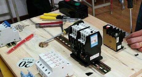
(3) Actuators. Circuit-breaker trip coils, closing coils and closing contactors, coils of AC contactors, electro-magnets in hydraulic and aerodynamic control devices (electrical control valves), etc.
(4) Signal components. For example, a signal indicating the state of the circuit breaker.
(5) Auxiliary contacts of circuit breakers and contactors.
Classification of control loopsThe control loop can be roughly divided into two categories:
(1) An independent control circuit separate from the main circuit. There is no electrical connection between this type of control circuit and the main circuit. The operating circuits of the high voltage equipment and important equipment are all separated from the main circuit by separate control circuits.
(2) Electrically connected circuit between the control circuit and the main circuit. Electromechanical devices powered by small and medium-sized motors (voltages below 380/220V), many use control circuits connected to the main circuit.
Control circuit voltage selection should pay attention to the problem
The control loop voltage often uses .24V, ~220V and ~380V, mostly ~220V. When the control line is long, the effects of balancing the line capacitance current and voltage loss must be considered. Reasonably select the control voltage.
The critical length of the wire
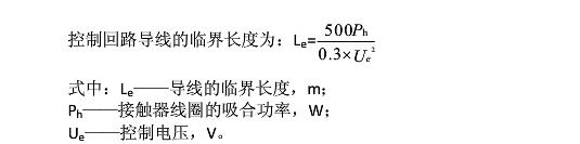
If the control line exceeds the critical length. When a stop command is issued, due to stray currents on the line (if the line is longer, the capacitance current of the line will be increased), the current will continue to maintain the contactor's pull-in, which may cause unstoppable failure.
Line pressure drop
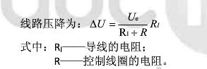
If the control circuit pressure drop is too large. When starting. The contactor cannot be pulled in, which can cause the device to fail to start.
Motor start control loopTo start the motor, it is not as simple as closing the brakes. There are many things that need to be done to achieve remote control and multi-point control. This article lists some of the most basic motor control loops. These are also essential elements when designing PLC circuits, except for the need for mechanical control during production.
Jog and linkage
Jog: The motor starts when the button is pressed and the motor stops when released.
Linkage: The motor starts when the button is pressed, and the motor continues to run after the button is released.
Circuit â–¼
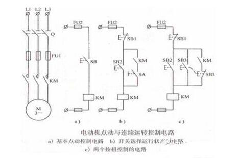
In the figure above, the left side is the main circuit, and the three a, b, c diagrams on the right are three different control loops.
In Fig. a, press the button SB, the motor starts and the motor stops when released. It is a typical jog control.
In Figure b, when the circuit breaker SA is open, push the button SB2, the contactor coil KM is energized, the normally open contact KM is closed, but there is a circuit breaker below the normally open contact KM to disconnect it, so while the motor Start, but it will stop after releasing. After closing the circuit breaker SA, press the button SB2, the coil of the contactor coil KM is energized, at this time the normally open contact KM is closed, so after the SB2 is released, the motor can still operate normally. At this point the motor is linked. Therefore, this figure can manually control the jogging or linked state.
In Fig. c, there is no circuit breaker and replaced by a mechanical interlock switch SB3. When the button SB2 is pressed, the contactor coil is energized, the normally open contact KM is closed, the motor is started, and after the release, since the normally open contact is still closed, the motor operates normally. When the button SB3 is pressed, the normally closed contact SB3 below the contactor's normally open contact is opened and the normally open contact of the contact SB3 is closed. The motor starts and the motor stops when released (the contactor normally open contact is not Access circuit). Therefore, this circuit can directly press SB3 and become a jog when the motor is linked.
When the motor is linked, after releasing the start button, the contactor coil is energized, the normally open contact KM is closed, and the motor can realize continuous operation. This concept is called “self-lockingâ€.
Motor jogging and interlocking are just a concept. No one wants their motors to move. Here we only need to know how to make the motor run continuously.
Remote control of the motor
This article takes two places to control the motor as an example. More control of the motor, generally divided into remote control and local control. That is, put the start button into a different button box, and then install the button box in the place where you need to control.
Circuit â–¼
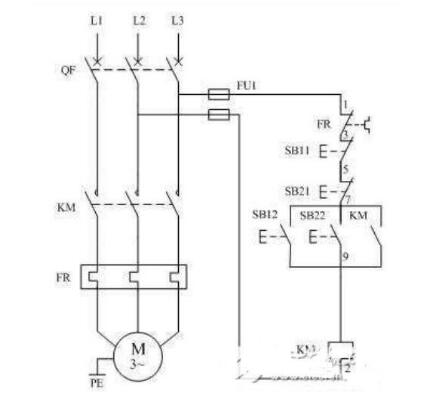
With the knowledge of jogging and interlocking, the role of the contactor KM in this diagram is unnecessary. In the figure, SB11 and SB21 are stop buttons, and SB12 and SB22 are start buttons. One of the start button and stop button is installed in the same button box, and the other two are also installed in another button box. Two button boxes can be placed next to the control room and the motor.
Physical connection diagram â–¼
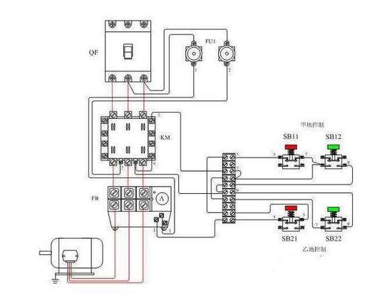
When remotely controlling the motor, it is only necessary to pay attention to that all the stop buttons are connected in series, and all the start buttons can be connected in parallel.
Motor start
Take the example of starting two motors M1 and M2 sequentially. It is required that M2 can be started after M1 starts, and M1 can be started independently.
Circuit â–¼
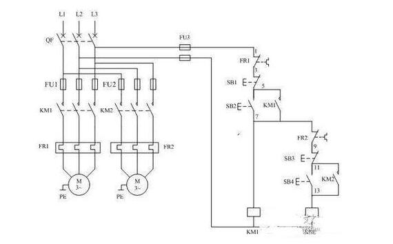
Among them, the buttons SB1 and SB3 are stop buttons which respectively control the motors M1 and M2; the buttons SB2 and SB4 are start buttons which control the motors M1 and M2, respectively. For ease of understanding, I have highlighted the control loop of M2 in the circuit diagram. That is, when the control loop of M2 is mentioned below, it refers to the one that protrudes to the far right in the figure above.
Similarly, the role of the contactor will not be repeated. As shown in the figure, when M1 is not running, that is, the normally open contact KM1 is not closed, and at this time, the control loop of M2 is disconnected, so when the start button SB4 is pressed, M2 does not respond. Only when M1 is running normally, KM1 is closed and the control circuit of M2 is powered. Then M2 can start normally.
Physical connection diagram â–¼
If multiple motors are needed to start simultaneously, there are two situations:
If other motors are required to start after M1 is started, then the control circuit of the motor is connected in parallel with the control circuit of M2.
If other motors are required to start after M2 starts, connect the control loop of the motor with the control loop of M2.
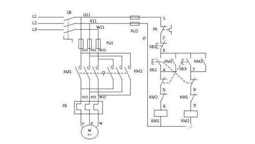
Positive rotation of motor
To realize the forward and reverse rotation of the motor, the principle used is to use two contactors to change the phase sequence of three-phase electricity.
Circuit â–¼
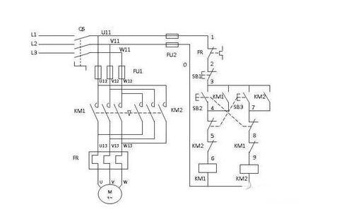
Pay attention to the main circuit on the left side. The order of the three items L1, L2, and L3 to the motor M1 through the contactor KM1 is left, center, and right. The order of reaching the motor M1 through the contactor KM2 is right, center, and left. The change of the phase sequence realizes the change of the motor running direction. This usage is used in electric cars or electric tricycles to achieve the reverse function. There is now a more convenient component called the "reverse switch", which is the principle.
For the convenience of description, it is assumed that the direction of rotation of the motor is positive when the SB2 circuit is closed. Hereinafter, the loop where the SB2 is located is a forward loop, and the loop where the SB3 is located is a reverse loop.
Let's look at the control loop. For ease of explanation, we have numbered the figures in the figure. Each number corresponds to the component directly above it. Similarly, the effect of the contactor normally open coils KM1 and KM2 is not repeated.
This diagram is well understood without the normally closed contacts of the two contactor NCs numbered 6 and number 9 and the two mechanically interlocked buttons numbered 5 and 8. That is, press SB2, the motor rotates forward, and press SB3 to reverse the motor.
A problem here is that if SB2 and SB3 are pressed at the same time or SB3 is pressed while the motor is rotating forward, it will cause a short-circuit accident. Therefore we have contactor NC contacts in the circuit. Connect the normally closed contact of KM2 in the forward control loop and the normally closed contact of KM1 in the reversed control loop. In this way, when the motor rotates in the forward direction, since the coil of the contactor KM1 is energized, the normally closed contact KM1 is in the OFF state, so even if the button SB3 is pressed at this time, there will be no reaction.
The normally closed contacts of the two contactors are respectively connected to the circuits in which the other contact is located. In this way, when one of the contactors is energized, the other contactor can no longer be energized. This is "interlocking."
At this time, we also faced a troublesome thing. When the motor is rotating forward, the only way to reverse it is to press the stop button and press the reverse button, which is very troublesome. For convenience, we use a mechanically interlocked push button and connect its normally closed contact to the adjacent control loop—number 5 and number 8 in the figure.
At this time, when the motor is rotating forward, we press SB3. At this time, the normally closed contact of No. 5 is disconnected, that is, the forward rotation circuit is de-energized. Therefore, the coil KM1 is de-energized, and the normally closed contact KM1 restores the closed state. The coil KM2 You can get electricity and the reverse circuit works normally. In this way, when the motor rotates forward and reversely, the stop button does not need to be pressed again.
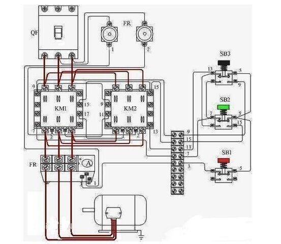
Physical connection diagram â–¼
Shenzhen Uscool Technology Co., Ltd , https://www.uscoolvape.com