How to read and understand homemade buzzer
The buzzer is an integrated electronic alarm device, which is powered by a DC voltage and is widely used in computers, printers, copiers, alarms, electronic toys, automotive electronics, telephones, timers and other electronic products as sounding devices. . Buzzers are mainly divided into two types: piezoelectric buzzer and electromagnetic buzzer. The buzzer is represented in the circuit by the letters "H" or "HA" (old standards are "FM", "ZZG", "LB", "JD", etc.).

1. The voltage type buzzer piezoelectric buzzer is mainly composed of a multivibrator, a piezoelectric buzzer, an impedance matcher, a resonance box, and a housing. Some piezoelectric buzzer housings are also equipped with light emitting diodes.
Multivibrators consist of transistors or integrated circuits. When the power is turned on (1.5~15V DC working voltage), the multivibrator starts to vibrate, and an audio signal of 1.5~2.5kHZ is output. The impedance matcher pushes the piezoelectric buzzer sound.
The piezoelectric buzzer is made of lead zirconate titanate or lead magnesium niobate piezoelectric ceramic material. A silver electrode is plated on both sides of the ceramic plate, and after being polarized and aged, it is bonded to the brass plate or the stainless steel plate.
2. Electromagnetic buzzer Electromagnetic buzzer is composed of oscillator, electromagnetic coil, magnet, diaphragm and shell.
After the power is turned on, the audio signal generated by the oscillator passes through the electromagnetic coil, causing the magnetic coil to generate a magnetic field. The vibrating diaphragm periodically vibrates and sounds under the interaction of the electromagnetic coil and the magnet.
Buzzer work sound principle:The sounding principle of the buzzer is composed of a vibration device and a resonance device, and the buzzer is further divided into a passive one and a second one.
The principle of the working phonation of passive passive excitation buzzer is as follows: The square wave signal input resonance device is converted into the sound signal output, and the schematic diagram of the working vocalization of the passive exciter buzzer is as follows:
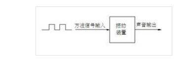
The work vocalization principle derived from the excitation buzzer is that the DC power input is subjected to an amplifying sampling circuit of the oscillation system to generate a sound signal under the action of the resonance device, and the working sound emission schematic diagram derived from the excitation buzzer is as follows:

There are many kinds of buzzer specifications, you need to know a few parameters (voltage, current, driving mode, size, connection/fixed mode), and of course, more important is the sound you want to get (sound pressure level, frequency level).
Operating voltage: Electromagnetic buzzer, from 1.5 to 24V, piezoelectric type from 3V to 220V are feasible, but generally piezoelectric or voltage is recommended to have more than 9V to obtain a larger sound.
Current consumption: Electromagnetic voltage varies from tens to hundreds of milliamperes. Piezoelectric saves more power. A few milliamperes can operate normally, and when the buzzer starts, instantaneously. Need to consume about three times the current,
Drive mode: Both types of buzzer have self-excited type, so long as they are connected to DC, they will sound, because the built-in drive circuit is in the buzzer. Because of the different operation principle, the electromagnetic buzzer The device uses 1/2 square wave to drive, piezoelectric square wave can have better sound output.
Size: The size of the buzzer will affect the volume level, the frequency of the frequency, the electromagnetic minimum from 7mm to the maximum 25mm, the piezoelectric type from 12mm to 50mm or more.
Connection method: Commonly used pins (DIP), wire, patch (SMD), piezo-type, and locking screws.
Sound pressure: The buzzer usually uses the distance of 10cm as the standard for testing. The distance doubles, and it will probably attenuate 6dB. Conversely, if the distance is doubled, it will increase 6dB. The electromagnetic buzzer can reach the level of 85dB/10cm. Piezoelectrics can do very loudly. Common alarms are mostly made of piezoelectric buzzer.
Homemade simple buzzer steps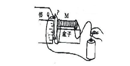
Required supplies: iron bolts, wires, transparent plastic, boxes, tins, scissors, wood, clips, about 6 cm long
Production Method:(1) Prepare the electromagnet M. Wind around 100 turns of the iron bolt about 6 cm long. Leave 5 cm at the end of the wire for the lead. Use a transparent tape to glue the coil so that the coil is not loosened and then tape it with a tape. The electromagnet on the box is ready
(2) Preparation of shrapnel P: Cut out a long iron piece with a width of about 2 cm from the tin can box, bend it at a right angle, connect one lead of the electromagnet to the shrapnel, and then glue the shrapnel against the wood board.
(3) Use the paper clip as the contact Q, use the book to put the paper clip up, stick it with tape, lead a wire, as shown in the figure to connect the circuit.
(4) Adjust the distance between M and P (by moving the box) so that the electromagnet can attract the shrapnel, adjust the distance between the contact and the shrapnel, so that they can just touch, you can hear the bee sound after power.
Power Meter is a monitoring and testing instrument which determines the power consumption of a connected appliance and the cost of the electricity consumed.
Built-in 3.6V rechargeable Batteries ( . The purpose of the batteries is to store the total electricity and memory setting
Resetting
If an abnormal display appears or the buttons produce no response, the instrument must be reset. To do this,
press the RESET button.
Display Mode
Entire LCD can be displayed for about 1 minute and then it automatically gets into Model. To transfer from
one mode to the other, press the FUNCTION button.
Mode 1: Time/Watt/Cost Display Display duration(how long) this device connect to power source.LCD on first line shows 0:00 with first two figures mean minutes(2 figures will occur while occur at 10 min) and the rest shows seconds. After 60mins, it displays 0:00 again with first two numbers meas hour(2 figures will occur at 10hours)and the rest shows minutes. The rest can be done in the same manner which means after 24 hours, it will re-caculate. LCD on second line displays current power which ranges in 0.0W 〜 9999W. LCD on third line displays the current electricity costs which ranges in O.Ocost 〜 9999cost. It will keep on O.OOcost before setting rate without other figures.
Mode 2: Time/Cumulative electrical quantity Display Display duration(how long) this device connect to power source.
LCD on first line shows 0:00 with first two figures mean minutes(2 figures will occur while occur at 10 min) and the rest shows seconds. After 60mins, it displays 0:00 again with first two numbers meas hour(2 figures will occur at 10hours)and the rest shows minutes. The rest can be done in the same manner which
means after 24 hours, it will re-caculate. LCD on second line displays current cumulative electrical quantity which ranges in 0.000KWH 〜 9999KWH without other figures. LCD on third line displays"DAY"- "1 'Will be showed on numerical part(the other three figures will be showed at carry) which means it has cumulated electrical quantity for 24hours(one day). The rest can be done in the same manner untill the maximal cumulative time of 9999 days.
Mode 3: TimeA^bltage/Frequency Display LCD on first line displays the same as Mode 1 dones. LCD on second line displays current voltage supply (v) which ranges in 0.0V 〜 9999V .LCD on third line displays current frequency (HZ) which ranges in 0.0HZ 〜 9999Hz without other figures.
Mode 4: Time/Current/Power Factor Display LCD on first line displays the same as Mode 1 dones.LCD on second line displays load current which ranges in 0.0000A 〜 9999A. LCD on third line displays current power factor which ranges in 0.00PF 〜 LOOPF without other figures.
Mode 5:Time/Minimum Power Display LCD on first line displays the same as Mode 1 dones. LCD on
second line displays the minimum power which ranges in 0.0W 〜 9999W. LCD on third line displays character of "Lo" without other figures.
Mode 6: Time/Maximal Power Display LCD on first line displays the same as Mode 1 dones. LCD on second line displays the maximal power which ranges in 0.0W 〜 9999W. LCD on third line displays character of "Hi" without other figures.
Mode 7: Time/Price Display LCD on first line displays the same as Mode 1 dones. LCD on third line displays the cost which ranges in O.OOCOST/KWH 〜 99.99COST/KWH without other figures.
Overload Display: When the power socket connects the load over 3680W, LCD on second line displays the''OVERLOAD[ with booming noise to warn the users,( 1918928,selectable choice)
Supplemental informations:
1: Except [OVERLOAD[ interface, LCD on first line display time in repitition within 24hours.
2: LCD on first line, second line or third line described in this intruction take section according to two black lines on LCD screen. Here it added for clarified purpose.
3. Mode 7 will directly occur while press down button "cost".
4. [UP"&"Down" are in no function under un-setting mode.
Setting Mode
1. Electricity price setting
After keeping COST button pressed lasting more than 3 seconds(LCD on third line display system defaults price, eg O.OOCOST/KWH ),the rendered content begins moving up and down which means that the device
has entered the setting mode. After that, press FUNCTION for swithing , then press "UP"and "DOWN" button again to set value which ranges in OO.OOCOST/KWH 〜 99.99COST/KWH. After setting all above, press COST to return to Mode7 or it will automatically return to Mode7 without any pressing after setting with data storage.
LCD Display Power Meter Socket,Power Meter Plug Outlet,Electricity Usage Monitor Socket,LCD Energy Power Meter Socket,Digital LCD Power Meter Socket
NINGBO COWELL ELECTRONICS & TECHNOLOGY CO., LTD , https://www.cowellsockets.com