LED digital tube 24-hour clock circuit experiment
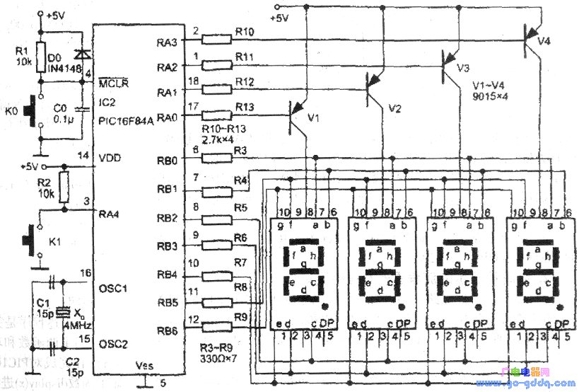
The clock is an electronic product that is very close to life. Here, a 4-digit LED digital tube is used to make a 24-hour clock circuit that can be placed in the home for timing. The circuit is shown below.
In the figure below, the RA4 bit of the PIC16F84A, the external K1 button is a key function key. The clock C program of the single-chip microcomputer is actually a counting method of the LED digital tube circulating in 0 to 24 hours. The starting time of this counting method starts from 0 o'clock, so the starting time must be started at the O o in the middle of the night. Work, so it is very inconvenient to use. To this end, a preset button should be added, as shown in the figure below, so that the clock circuit of the following figure can be used to calibrate the start time of the clock in real time after the power is connected at any time. At the start time of the calibration clock, here The minute and hour displays are subject to change, excluding the second display.
1. The operation method of the clock circuit below
Here is the operation method of the 4-bit LED digital tube clock circuit shown in the figure below. The purpose is to explain the key function function required in the writing of the following clock program, which is also the requirement of the hardware circuit necessary for writing the C program.
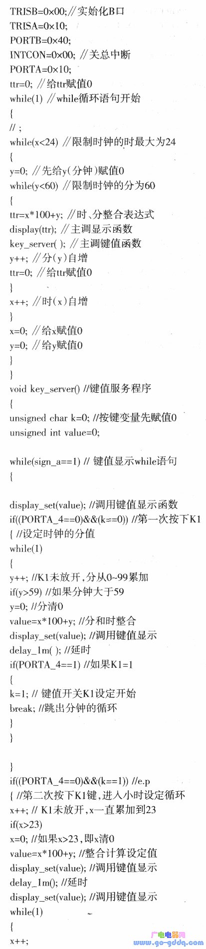
When the following C program is edited, compiled, and the .hex (target code) is programmed to the PIC16F84A chip, the chip is placed on the socket in the figure below (the 10-pin jack can be placed on the board for easy operation) The chip works), connected to the +5V power supply (not shown here, the relevant power adapter can be used), the board below shows 00.00. At this time, if the Kl key is not pressed, the circuit board is a clock circuit that starts from 0 and is connected to 0 to 24 hours. At this time, the circuit board of the following figure can be used as a timer. If you want to make the board a real-time clock, for example, the current time is 12.32 or 10:32. At this time, by pressing the Kl key manually, 00.00 disappears, then manually release the Kl key, and then manually press the Kl key. At this time, 00.00 starts counting from the minute, until the display of 0.32 (minutes), manually release the Kl key. Then press the Kl key to start the hourly pre-value. Until 00.32 changes to 12 o'clock, when the LED digital tube displays 12.32, manually release the Kl key, the preset real-time function is completed, and the following circuit board starts the 0~24 hour cyclic operation timing according to the real-time (can be set) time.
2. The C program can be pre-valued from 10 minutes to 24 hours.
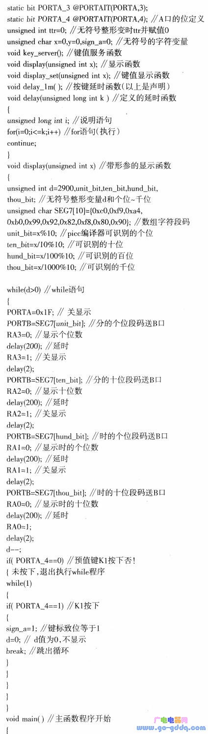
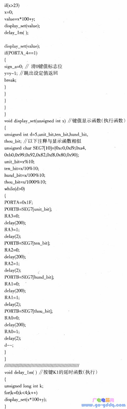
The above-mentioned pre-settable clock circuit operation method, and then extending the 0 to 99 second increment program of PICl.c, can edit the preset C program of 0 minutes to 24 hours, and named it as PIC2.c. The list is as follows:
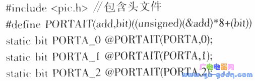
Description:
(1) The C program is used multiple times, that is, it is fully executable. It was also successful to edit this function in assembly language in the early days, but its program entry is more than double that of the C language program here. If you are interested, you can optimize the PIC2.c to reduce the code entry of the program.
(2) The best way to read the above clock program is to first make a circuit board according to Figure 1, then compile PIC2.c on MPLABIDE (such as version 7.40) to generate the target code.hex, then burn hex to pic16F84A On the chip, then make the clock below. Then repeat the operation according to the clock circuit operation method described above, and then read the above program, it will be clear at a glance.
(3) When reading PIC2.c, you should still pay attention to the birth function dispfay(ttr) in the program: here the actual parameter ttr in the main function has an expression ttr=X*l00+Y, instant and minute integration expression The actual value of the calculation after completion is different from the simple implementation of PICl.c. Similarly, the argument of the calling function is passed to the called function Voiddisplay (unsignedint), that is, after the value is passed, the display function is completed.
Use the same method to read the main function maln call key value display function display_set (val-ue); to complete the value transfer process, not repeated here.
(4) The accuracy of the above-mentioned preset 0 to 24 hour clock is mainly determined by the unsignedintd=2900 in the called function (execution function), that is, its d value, which is d=2900, and the clock ratio of the value is The time is slightly slower. When the reader is interested in using it, the d can be appropriately reduced, and then the CCTV standard time is better!
Tws Sport Earphone,True Wireless Earbuds,Tws True Wireless Stereo,Tws True Wireless Earbuds
Guangzhou YISON Electron Technology Co., Limited , https://www.yisonearphone.com