Orthogonal Frequency Division Multiplexing Technology and Its Application
1 Development of orthogonal frequency division multiplexing (OFDM) technology
The concept of OFDM was proposed in the 1950s and 1960s, and the OFDM patent was published in 1970 [1]. Its basic idea is to adopt the frequency division multiplexing (FDM) method that allows the sub-channel spectrum to overlap but does not affect each other. Transfer data in parallel. The early applications of OFDM include AN / GSC_10 (KATHRYN) high-frequency variable-rate digital modems [1].
In the early OFDM systems, the subcarrier array required by the transmitter and related receivers was generated by a sinusoidal signal generator, and the system was complicated and expensive. In 1971, Weinstein and Ebert proposed the use of discrete Fourier transform to implement all modulation and demodulation functions in OFDM systems [3], which simplifies the problem of strict synchronization between local array carriers in the oscillator array and related receivers. The all-digital program made theoretical preparations.
After the 1980s, OFDM modulation technology has once again become a research hotspot. For example, in the research of cable channels, Hirosaki used OFDM modulation technology completed by DFT in 1981, and successfully tested 16QAM multi-channel parallel transmission 19.2kbit / s phone line MODEM [4].
Since the 1990s, the application of OFDM has involved the use of mobile frequency modulation (FM) and single sideband (SSB) channels for high-speed data communications, land mobile communications, high-speed digital subscriber loop (HDSL), and asymmetric digital subscriber loop ( ADSL), ultra-high-speed digital subscriber loop (VHDSL), digital sound broadcasting (DAB) and high-definition digital television (HDTV) and terrestrial broadcasting and other communication systems.
2 Principle of OFDM
OFDM technology is a multi-carrier modulation technology, which is characterized in that each sub-carrier is orthogonal to each other.
Let {fm} be a set of carrier frequencies, and the relationship between each carrier frequency is:
{fm} = f0 + m / T m = 0,1,2,… N-1 (1)
In the formula, T is the duration of the unit code, and f0 is the transmission frequency.
The unit signal group as a carrier is defined as [16]:

The physical meaning of l in the formula corresponds to "frame" (that is, there are m parallel codes sent at the lth time).
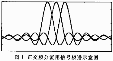
Its spectrum overlaps with each other, as shown in Figure 1.
As can be seen from Figure 1, OFDM is composed of a series of equally spaced subcarriers in frequency, each subcarrier is modulated by a digital symbol, and the signal power form on each carrier is the same, all of which are sinf / f type. Corresponds to the square wave in the time domain.
Φm (t) satisfies the orthogonal condition

as well as

The symbol "*" indicates conjugation.
When a digital signal represented by a set of complex numbers {Xm, l} taken from a finite set modulates φm, then:

This S (t) is the OFDM signal, where Sl (t) represents the OFDM signal of the lth frame, Xm, l (m = 0,1, ..., N-1)
It is a cluster of signal points, which are respectively transmitted on the m-th subcarrier of the l-th frame OFDM.
At the receiving end, Xm, l can be demodulated by

This is the basic principle of OFDM. When multipath propagation occurs in the transmission channel, the orthogonality between the received subcarriers will be destroyed, so that mutual interference will occur between the front and back transmission symbols on each subcarrier and between each subcarrier. To solve this problem, a guard interval is inserted before each OFDM transmission signal, which is periodically extended from the OFDM signal. As long as the multipath delay does not exceed the guard interval, the orthogonality between subcarriers will not be destroyed.
3 Implementation of OFDM system
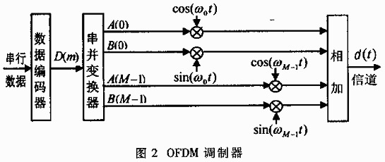
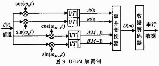
From the above analysis, in order to realize OFDM, it is necessary to use a set of orthogonal signals as subcarriers. Typical quadrature signals are {1, cosΩt, cos2Ωt, ..., cosmΩt, ..., sinΩt, sin2Ωt, sinmΩt, ...}. If such a set of orthogonal signals is used as a sub-carrier, a non-return-to-zero square wave with a symbol period of T is used as a baseband code pattern, which is modulated and transmitted through a wireless channel. At the receiving end, such a set of orthogonal signals are used in [0, T] to perform correlation operations with the transmitted signal to achieve demodulation, and then the original signal is recovered. The basic principle of OFDM modulation and demodulation is shown in Figure 2 and Figure 3.
At the modulation end, the serial binary data to be sent through the data encoder (such as 16QAM) to form M complex sequence, where D (m) = A (m)-jB (m). This complex sequence is transformed by a serial-to-parallel converter to obtain an M parallel code (one frame) with a symbol period of T. The code pattern is a non-return-to-zero square wave. Use this M parallel codes to modulate M subcarriers to achieve frequency division multiplexing. The resulting waveform can be expressed by the following formula:

In the formula: ωm = 2πfm, fm = f0 + mΔf, Δf = 1 / T is the frequency interval between each subcarrier; f0 is the integral multiple of 1 / T.
At the receiving end, perform a correlation operation on d (t) with a sine or cosine signal with frequency fm in [0, T] to obtain A (m) and B (m), and then arrive at the parallel and serial variable and decode the data Then restore the same data sequence as the sender.
The equipment required for this early implementation method is very complicated. When M is large, a large number of sine wave generators, filters, modulators, and related demodulator devices are required. The system is very expensive.
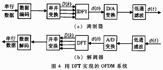
In order to reduce the complexity and cost of the OFDM system, people consider using Discrete Fourier Transform (DFT) and its inverse transform (IDFT) to achieve the above functions. The above formula (7) can be rewritten as follows:

If d (t) is sampled at fs = N / T = 1 / (Δt) (N is a positive integer greater than or equal to M, its physical meaning is the number of channels, where N = M) (satisfies fs > 2fmax, fmax is the highest frequency of the spectrum of d (t), which can prevent frequency aliasing), then the N-point discrete order d (n) can be obtained within the main value interval t = [0, T], where n = 0 , 1, ..., N-1. The sampling time is t = nΔt, then:

It can be seen that the above formula happens to be the real part of the inverse discrete Fourier transform (IDFT) of D (m), namely:
d (n) = Re [IDFT [D (m)]] (10)
This means that if IDFT is performed on the transmitter (D), the result is sent to the receiver through the channel, and then DFT is performed on the received signal, and then the original signal D (m) can be recovered without distortion. ). In this way, the discrete Fourier transform can be used to realize the modulation and demodulation of the OFDM signal. The implementation block diagram is shown in FIG. 4.
Using DFT and IDFT to realize the OFDM system greatly reduces the complexity of the system and reduces the system cost, laying a foundation for the wide application of OFDM.
4 Computer simulation of OFDM implementation
As can be seen from the previous section, to realize OFDM, the traditional multi-path orthogonal subcarrier modulation can be used, or the Fourier transform can also be used. The system complexity and cost of these two methods are very different. At present, all practical OFDM systems adopt the Fourier transform implementation method. Compared with the traditional method, this method greatly simplifies the system configuration and reduces costs. The computer simulation method is used here to simulate the two methods, further illustrating that the two methods have the same system effect.
The simulation system is realized by Matlab. The source data uses a waveform file. After sampling, there are 680 serial data, which are divided into 34 frames. Each frame of 20 data constitutes the real part and imaginary part of the 10-channel code.
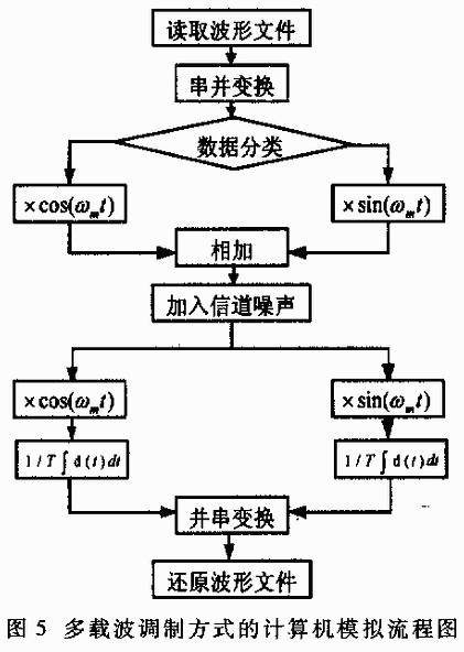
In the multi-path orthogonal subcarrier modulation method, ten orthogonal codes are respectively modulated with 20 orthogonal triangle waves, and the results are added together as a modulated wave. At the receiving end, these 20 triangle waves are used to demodulate the received wave and compare the demodulated data with the source data. The program flow chart is shown in Figure 5.
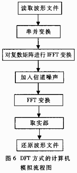
In the Fourier transform method, the fast Fourier algorithm is used to directly perform IFFT on each frame of data to obtain a modulated sequence. Perform FFT on the received sequence at the receiving end to restore the original data. The program flow chart is shown in Figure 6.
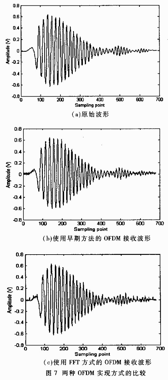
In order to simulate the wireless communication environment, low amplitude Gaussian noise is added to the channel. Figure 7 shows the source data waveform and the OFDM output waveform obtained in two ways. It can be seen that the same system effect is obtained in both ways.
5 Application of OFDM system in broadband communication
(1) Digital Sound Broadcasting Project (DAB)
The European Digital Audio Broadcasting Project (DAB)-DABEUREKA147 project has successfully used OFDM technology. In order to overcome the possible accent phenomenon caused by multiple base stations, people added a certain protection time slot in front of the OFDM signal, effectively solved the co-frequency interference between the base stations, realized the single frequency network broadcast, and greatly reduced the entire broadcast occupied frequency band width.
(2) High-definition television (HDTV)
Since the existing dedicated DSP chip can complete the 1024-point FFT within 100 μs at the fastest, this can meet the needs of video transmission within the bandwidth of 8 MHz, thus providing the possibility of being applied to video services. At present, Europe has taken OFDM as the basis for the development of terrestrial digital TV; Japan has also used it for the development of portable TVs and on-board TVs installed in coaches and taxis.
(3) Satellite communications
VSAT's satellite communication network uses OFDM technology. Since the communication satellite is a stationary satellite above the equator, OFDM does not need to set a guard interval. The use of DFT technology to achieve OFDM will greatly simplify the complexity of the master station equipment, especially suitable for small The station sends different information.
(4) HFC network
HFC (Hybrid Fiber Cable) is a hybrid fiber / coaxial network. Recently, OFDM has been applied to cable television networks, using optical fiber transmission on trunk lines, while coaxial cables are still used in user distribution networks. This photoelectric hybrid transmission method improves the image quality, and can be transmitted to a far place, expanding the use of cable TV.
(5) Mobile communication
In the mobile communication channel, the delay spread caused by multipath propagation in urban areas is roughly a few microseconds to tens of microseconds, which will cause inter-symbol crosstalk and deteriorate system performance. In recent years, people abroad have studied the use of multi-carrier parallel transmission 16QAM modulation mobile communication system. Combining OFDM technology with interleaving technology and channel coding technology can effectively combat inter-symbol interference, which has become the research direction of anti-fading technology in the mobile communication environment.
OFDM technology is one of the communication technologies that has been rapidly developed in recent years. Because it can effectively overcome the fading in multipath propagation, eliminate inter-symbol interference, and improve spectrum utilization, it has been widely used in broadband communications. In the early OFDM system, a set of orthogonal functions were used as subcarriers, and a large number of sine wave generators and modems were used. The system was complex and costly. The Fourier transform method can effectively reduce the system complexity and reduce the system cost. Computer simulations of these two implementations show that the two methods have the same system effect.
TV Antenna Description
1. Receives free broadcast High Definition TV signals (such as ABC, CBS, NBC, PBS, and Fox).
Supports 1080i, 1080 and 720p.2. UHF/VHF indoor antenna,
Suitable for DTV/HDTV/HD/DTC receiver, also support PC and NB when with connect.
3. Easily hidden behind a picture, bookshelf or television.
4. Fast and easy set up with 3 steps - Unwrap, Plug it in and Scan channels.
5. Very convenient,You can put it higher on wall; lay flat on table; place it high on window (strongly recommended), and it will provide you with opportunities to watch crystal clear digital & HD shows! If you don't want to mount the antenna on the wall/window.
6. If your location's HDTV digital terrestrial signal is weak or your place is far away from broadcast tower, you need to buy High Gain TV Antenna Amplifier.
7. Specially designed circuit produces exceptional reception with compact size.
TV Antenna Specification
Frequency Range (MHz): 174-230MHz /470-862MHz
Input Impedance (Ω): 75
V.S.W.R: ≤1.6
Gain (dBi): 25-30
Radiation: Omni
Connector: F or IEC
Cable Type: RG174
Cable Length:Typical 3M
Picture show

TV Antenna
TV Antenna, Digital Indoor TV Antenna, Outdoor TV Antenna Manufacturers and Suppliers in China
Shenzhen Yetnorson Technology Co., Ltd. , http://www.yetnorson.com