[Popular] PC main hardware CPU, motherboard, graphics card power requirements
In fact, the hardware in our PC has different requirements for the supply voltage, so the PC power supply should output different voltages for different hardware. Just why are the output powers of these voltages different? What is the specific voltage required for specific hardware? We believe that most players are awkward after seeing these two questions.
Now we can easily pull out a regular PC power supply. We can see the output specifications of +12V, +3.3V, +5V, -12V and +5VSB on the nameplate. These 5 voltages are also the internal hardware of the PC host. The supply voltage that needs to be used. However, not every hardware will use these voltages. In fact, their needs are different, so let's take a look at the power supply voltage requirements of the main hardware inside the PC, namely CPU, motherboard, memory, graphics card, and hard disk. .
Main board and memory supply voltage requirements:First of all, we start from the motherboard. The status of the motherboard in the PC is like a bridge on the ground. The power supply and data exchange of CPU, graphics card, memory and other hardware need to be completed by the motherboard. There are two main interfaces connected to the main board. One is the CPU-specific power supply interface. We will talk about this interface later; the other is the 24pin main power supply interface, which is also the largest power supply interface in the PC. Power is supplied from various hardware on the motherboard.
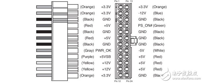
24pin main power supply interface, 5 voltages are involved
The 24pin power supply interface on the motherboard uses all five power supply voltages on the PC power supply, namely +12V, +3.3V, +5V, -12V and +5VSB, in addition to a -5V, but the hardware and interface corresponding to this voltage In fact, it has already been eliminated, so the current PC power supply no longer provides -5V power supply. This way in the 24pin interface is only a nominal existence.
The main power supply of the various onboard chips on the motherboard is +5V and +3.3V, while the +12V is mainly used for PCI-E, PCI slots and fan interfaces. The PCI-E slot is in addition to +12V. It also uses +3.3V power supply, and the PCI slot requires +12V, -12V and +5V. The power supply used in the memory slot is +3.3V, but it is additionally equipped with a voltage conversion circuit that converts +3.3V into a working voltage of the memory such as 1.5V, 1.2V, etc., and then supplies it to the memory.
The USB interface is mainly powered by +5V, so for players who need to connect a lot of USB devices, the output power of the +5V power supply should not be too small. The -12V power supply actually needs a small chance to use, that is, it does not need high power, because it only uses the level judgment for the serial port or PCI interface device, so the -12V output power of the PC power supply does not exceed 10W. Even lower.
Among the motherboard power supply requirements, +5VSB is a special existence. +5VSB is also called +5V standby, because this way is actually not needed in the power-on state, but it needs to be used in the shutdown state. +5VSB starts to output immediately after the power cable is connected to the power cable and the switch is turned on. It mainly provides standby current to the main chip on the motherboard, which is convenient for quick wake-up and booting. In addition, some motherboards still support charging the mobile phone through the USB interface in the off state, and also need to use +5VSB. Therefore, many power supplies now pay more attention to the output current of +5VSB, which is generally not lower than 2A.
CPU supply voltage requirements: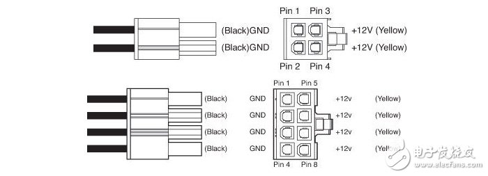
Power supply CPU power supply interface, available in 4pin and 8pin, providing +12V power supply
The CPU installed on the motherboard can be said to be a very special existence. Because of its high power consumption, in order to ensure the normal operation of the CPU, its power supply is independent, not from the 24pin interface, but through dedicated 4pin or 8pin interface for power supply, what is needed is +12V power supply, and then converted to the working voltage of the CPU through the switching power supply circuit on the motherboard.
It should be noted that the power supply interface of the CPU has 4pin and 8pin. The latter has a stronger power supply capability. However, in general, the 4pin interface on the 8pin interface can also be turned on, which can also meet the normal use requirements. However, if you need overclocking, or if you are using a high-end CPU, and the motherboard has an 8pin CPU power supply interface, we recommend to buy a power supply with the corresponding interface to ensure the stability of the whole machine!
Graphics card supply voltage requirements: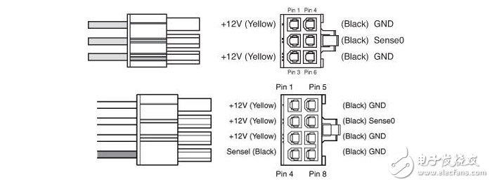
Graphics card external power supply, 6pin and 8pin, providing +12V power supply
Now the mainstream interface of the graphics card is the PCI-E interface, so there are two kinds of power supply voltages required, one +3.3V and the other one is +12V. Among them, +3.3V is mainly the power supply of I/O chip and peripheral circuit, the power consumption is not high, it can be obtained directly from PCI-E slot; and +12V needs to be supplied to GPU and video memory, which can be said to be the main video card. The power supply source, in addition to the PCI-E slot, the mid- to high-end products need to be obtained from the external 6pin or 8pin power supply interface.
The external power supply interface of the graphics card mainly provides +12V power supply. Similar to the CPU power supply interface, the power supply capability of the 8pin interface is stronger than that of the 6pin interface, and most of the graphics cards need to be connected to the corresponding external power supply interfaces before they can work normally. In fact, in the hardware power consumption of the PC, the graphics card has already occupied a large part. It can be said that it and the CPU together occupy nearly 80% of the power consumption of the whole machine.
Power requirements for mechanical hard drives and solid state drives (SSDs):Today's hard drives are divided into two major camps: mechanical hard disk HDD and solid state hard disk (SSD). Although the power supply interfaces they use are all SATA power supply interfaces, the voltages they need are not exactly the same. The 3.5-inch mechanical hard disk requires +12V, +5V and +3.3V, of which +12V is for the motor, +5V and +3.3V for the main control circuit, and the 2.5-inch hard drive only requires + 5V and +3.3V, because the latter's motor power consumption is relatively low, +5V power supply can be satisfied.
However, the main control circuit of the current mechanical hard disk does not necessarily need +3.3V power supply, because most of them have their own +5V to +3.3V voltage conversion circuit, so even if only +12V and +5V power supply can work normally. The opportunity to use +3.3V has actually been greatly reduced.
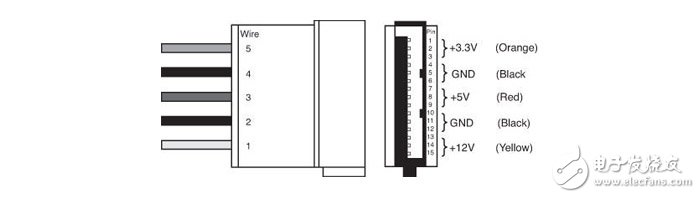
SATA power supply interface, including +3.3V, +5V and +12V power supply
Solid-state drives (SSDs) have both SATA and PCI-E interfaces. The former mainly uses +5V and +3.3V, but for the sake of power compatibility, they also do +5V to +3.3V internally. The voltage conversion circuit, or directly use a chip compatible with two voltages, so in fact, the solid state drive of the SATA interface only needs to have a +5V power supply to work properly.
The SSDs of the PCI-E interface (including the M.2 interface) will be powered by +3.3V and can be obtained directly from the PCI-E slot. Some PCI-E interface solid state drives will use +12V power supply. This is because the standard adapter card or even its own body with voltage conversion circuit will convert +12V into a suitable voltage for the solid state drive.
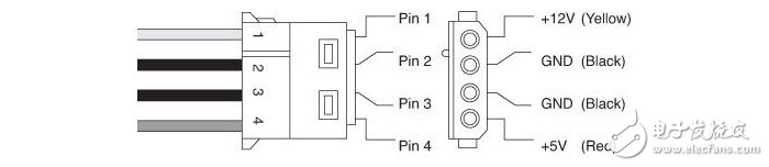
The D-type 4pin interface has a long history and can provide +12V and +5V power supply.
The problem of +5V and +3.3V voltage compatibility inside the hard disk just mentioned is actually a "historical legacy problem", because the early IDE interface hard disk uses the old D-type 4pin interface, this interface is only +12V and +5V power supply. At the beginning of the promotion of the SATA interface, since not every power supply has a SATA interface, it is inevitable to transfer the SATA power supply interface from the D-type 4pin interface. The former does not have a +3.3V power supply. Considering hardware compatibility, virtually all SATA interface products can be used out of +3.3V.
What is a fiber optic slip ring?
A fiber optic slip ring is a device that allows for the transfer of data, power, and signals between two rotating objects. The ring is made up of one or more optical fibers that are used to transmit light signals. These signals can be used to send power, data, or other signals between the two objects. The fiber optic slip ring is a newer technology that has many benefits over traditional slip rings.
How do fiber optic slip rings work?
A fiber optic slip ring is a device that allows electric current and optical signals to pass through a rotating joint. This is often used in applications where it is necessary to transfer data or power between two stationary points while the object rotates. The fiber optic slip ring uses light rather than metal to conduct these signals, which makes it ideal for use in high-speed or hazardous environments.
Types of fiber optic slip rings
When it comes to telecommunications, fiber optics are king. They're the backbone of almost every network today, and they're getting faster and more reliable all the time. That's thanks in part to a technology called fiber optic slip rings.
Advantages of fiber optic slip rings
A fiber optic slip ring is a device used in optical communication. It is a component of many fiber optic networks and it allows for the transmission of data over long distances without losing signal quality. Fiber optic slip rings are also used to improve the performance of other optical systems.
Disadvantages of fiber optic slip rings
Fiber optic slip rings are growing in popularity for rotating applications. Fiber optic slip rings provide many advantages over traditional electrical slip rings, including much smaller size, weight, and power consumption. However, fiber optic slip rings also have a few disadvantages. One disadvantage is that they can be more expensive than traditional electrical slip rings. Additionally, fiber optic cables are more fragile than electrical cables, so they can be more susceptible to damage.
Conclusion: What are the benefits and drawbacks of fiber optic slip rings?
When it comes to fiber optic slip rings, there are both benefits and drawbacks to consider. On the one hand, fiber optic slip rings offer a number of advantages over traditional metal contact slip rings. They are lighter in weight, which makes them easier to install and transport. They also generate less heat, making them safer to use in hazardous environments. Additionally, they provide superior performance in terms of electrical noise and signal integrity.
However, fiber optic slip rings also have some drawbacks. They are more expensive than traditional metal contact slip rings, and they can be more difficult to repair if they malfunction. Additionally, they may not be suitable for some applications due to their limited range of motion.
Fiber Optic Slip Ring,Brass Slip Ring,Fiber Optic Silp Ring,Electrical Rotary Joint
Dongguan Oubaibo Technology Co., Ltd. , https://www.sliproubos.com