PWM control of a new switching power supply
In order to achieve miniaturization and light weight of the power electronic power system, high-frequency switching power supplies are required, which requires the use of fully-controlled power electronic devices. And their turn-on and turn-off is a kind of power supply that uses PWM control technology to control its turn-on and turn-off, so that the output voltage of the main circuit is stable.
1, switching power supply control circuit principleThe switching power supply control circuit should generally have the following functions: a fixed frequency oscillator whose frequency can be preset in a wide range, a pulse width modulation function with adjustable duty ratio, a dead time calibrator, and one or two paths with a certain driving power. The output of the totem pole circuit, disable, soft start and current, voltage protection functions. The pulse width control circuit is the core part of the switching power supply. At present, there are a variety of integrated pulse width control circuit devices. Figure 1 shows the basic principle diagram of the pulse width controller.
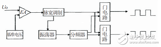
Figure 1 Schematic diagram of pulse width modulation circuit
2, control circuit designThe control circuit is mainly composed of an electronic control circuit and a drive circuit, and the pulse width modulation circuit in the control circuit is the core of the entire power control system, and it has direct contact with other circuits in the control system, and its main function is to give a voltage The signal and voltage feedback signals are compared and amplified, and according to the difference between the given value and the feedback value, a pulse signal of a corresponding width is output to adjust the output voltage of the power source. The PWM method of constant frequency modulation is usually used to achieve the characteristic control required by the controller. The pulse width modulation circuit also has protection functions such as undervoltage, overvoltage and overcurrent, which block the output pulse and stop the output of the power supply. In addition, the pulse width modulation circuit also has functions such as soft start and dead zone setting.
2.1, pulse width modulation circuitThis design uses SG3525 as the PWM control chip for the power supply. The chip is simple to use and requires only a small amount of external resistors and capacitors to form the required pulse width modulation circuit. As shown in FIG. 2, the inside of the chip is mainly composed of an error amplifier N1, a comparator N2, an oscillator, a phase splitter, and a flip-flop.
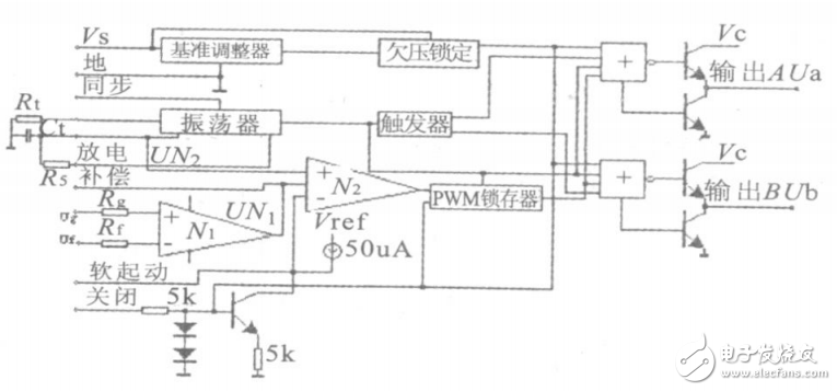
Figure 2 Pulse width modulation circuit diagram
The switching frequency is determined by the external timing resistor Rt and the timing capacitor Ct, and the oscillation frequency is as shown in Equation 1.
Fs=1/(Ct(0.7Rt+3R5))(1)
In order to prevent the bridge arm from passing through, there is a dead time, the value of which is determined by R5 and Ct. The duty cycle of the signal varies with Ug. The higher the Ug, the larger the output of N1 and the larger the duty cycle of the N2 output pulse, thus achieving pulse width modulation.
The terminal is used to facilitate the connection of wires. It is actually a piece of metal enclosed in insulating plastic. There are holes at both ends to insert wires. There are screws for fastening or loosening, such as two wires, sometimes Need to connect, sometimes need to be disconnected, then you can use the terminal to connect them, and can be disconnected at any time, without having to solder or twist them together, very convenient and fast.
Power Terminal Block,High Power Terminal Connector Block,Power Terminal Block Connector,Ac Power Terminal Block
Sichuan Xinlian electronic science and technology Company , https://www.sztmlchs.com