Read the origin and type of the oscilloscope
The Nobel Prize winner, German physicist KF Braun (Fig. 1) invented the CRT oscilloscope in 1897 for his curiosity about physical phenomena. He applies an oscillating signal to the horizontal deflection plate on the fluorescent CRT and then sends a test signal to the longitudinal deflection plate. These two deflectors produce a transient image of the wave on the small screen. The invention evolved (Figure 2) into a measuring instrument and its performance continued to improve over the next 50 years. The improvements made by engineer Howard Weilin in 1947 made the oscilloscope a very practical instrument, and for the first time it was possible to control the scanning function with triggers.
Figure 1: Nobel Prize winner, physicist KF Braun
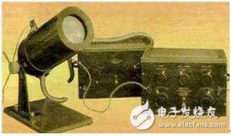
Figure 2: Early oscilloscope
Early oscilloscopes lacked the trigger, so the waveform of the input voltage could only be tracked horizontally when the input voltage exceeded the adjustable threshold. The trigger function maintains a stable repetitive waveform on the CRT, that is, repeatedly draws waveforms of the same trajectory. If there is no trigger function, the oscilloscope will display multiple scan waveforms in different positions, resulting in inconsistent clutter or moving images on the screen. The direct drivers of continuous improvement in the performance and functionality of oscilloscopes are high-performance analog and digital semiconductor devices, and the rapid development of software.
The call of the digital age
Thanks to faster analog-to-digital conversion speeds and memory for recording and displaying waveforms, digital oscilloscopes began to emerge in the 1980s and quickly became popular.
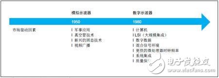
Figure 3: The market drive for analog oscilloscopes to evolve into digital oscilloscopes
Even the earliest digital oscilloscopes offer the flexibility of triggering, analysis, and display that analog oscilloscopes do not have. The development of semiconductors and software has further transformed the instrument from a simulation-based structure to a digital-based structure. Signal processing in the digital arena has created favorable conditions for commercial and industrial products, and oscilloscopes have benefited a lot. In a nutshell, digital oscilloscopes not only process signals in an unprecedented way, but also analyze signals more widely, while also meeting the special measurement requirements of more complex and higher-rate data streams. These are just numbers. Part of the many advantages of an oscilloscope. Digital oscilloscopes allow the user to capture specific events based on certain parameters of the signal, as well as the situation before the event. Thanks to the LAN and the Internet, users can remotely operate the oscilloscope and display the results in another room, another town, or even another country, making it an integral part of the automated inspection system. A key part of the digital oscilloscope architecture is the digital trigger system introduced by Rohde & Schwarz in 2009, which eliminates the inherent limitations of analog trigger systems (such as trigger jitter). The digital trigger system is described in more detail below.
Type of digital oscilloscopeDigital oscilloscopes have two basic functions: signal acquisition and signal analysis. During the acquisition of the signal samples, the acquired signals are stored in memory; in signal analysis, the oscilloscope analyzes the acquired waveforms and outputs them to the display. There are a variety of digital oscilloscopes on the market today, and here are the most common types of oscilloscopes available today.
Digital sampling scope
The digital sampling oscilloscope samples the signal before it is vertically set. It has a very wide bandwidth, the disadvantage is that the dynamic range is limited, and the peak-to-peak value of the measured signal is generally about 1 V. Unlike some other types of digital oscilloscopes, digital sampling oscilloscopes can capture frequency components in the signal that are much higher than the instrument's sample rate. It measures faster repetitive signals than other types of oscilloscopes. As a result, digital sampling oscilloscopes can handle ultra-high-bandwidth application measurements, such as fiber-optic transmission measurements, which are also costly.
Real time sampling oscilloscope
When the frequency range of the signal is less than half of the maximum sampling frequency of the oscilloscope, real-time sampling has obvious advantages. This technology allows the instrument to acquire a large number of sample points in a single scan, providing a highly accurate display. This is currently the only way to capture the fastest single-shot transient signal.
Embedded systems typically contain digital logic signals, as well as clocked or uncontrolled clocked parallel and serial buses, as well as standardized or dedicated transmission patterns.
All of these signals must be analyzed, which often requires the use of complex test equipment and multiple instruments. And usually both analog and digital signals must be displayed. To this end, many of today's oscilloscopes have specific options to upgrade digital oscilloscopes to hybrid tools with logic analysis capabilities. This is very important for fast debugging of digital circuits because of its digital triggering, high resolution, acquisition and analysis capabilities.
Mixed signal scope
Mixed-signal oscilloscopes extend the capabilities of digital oscilloscopes, including logic and protocol analysis capabilities, simplifying the test platform and enabling simultaneous visualization of analog waveforms, digital signals, and protocol analysis for a single instrument. Hardware developers can use mixed-signal oscilloscopes to analyze signal integrity, and software developers can use them to analyze signal content.
A typical mixed-signal oscilloscope has two or four analog channels, as well as more digital channels. Analog and digital channels require synchronization so that they can be correlated in time and analyzed on the same instrument.
Mixed domain
As the name implies, a mixed-domain oscilloscope can display waveform data in the digital, analog, and RF domains and establish correlations between them, each of which displays the signal in a different manner. This is useful in many measurement applications. For example, if a user needs to look at analog, digital, and high-frequency signals across subsystems when evaluating an embedded (board-level) signal processing system, a hybrid domain oscilloscope can meet the requirements. Basic elements of a digital oscilloscope
Each digital oscilloscope has four basic functional blocks – vertical, horizontal, trigger, and display. In order to understand the overall function of a digital oscilloscope, it is important to understand the function of each module.
Most areas of the front panel of the digital oscilloscope are used to control vertical, horizontal, and trigger functions, as most of the required adjustments are done by these functions. The vertical function section controls the attenuation or amplification of the signal by changing the value of "volts per division" by the control so that the signal can be displayed at an appropriate amplitude. The horizontal controls are related to the time base of the instrument, and its "seconds per second" control is used to determine the amount of time represented by the horizontal level on the display. The trigger system performs basic functions such as signal stabilization and oscilloscope initialization for signal acquisition. The user can select and modify the specific trigger type. The final display system includes the display itself and the display driver, as well as software for performing display functions.
Vertical systemThe system (Figure 4) allows the user to vertically position and scale the waveform, select the input coupling method, and modify the signal characteristics to display it on the screen in a specific manner. The user can place the waveform vertically at the exact position on the display and increase or decrease its size. All oscilloscopes have a grid on the display screen that divides the viewable area on the screen into 8 or 10 vertical grids, each of which represents a portion of the total voltage. That is, for an oscilloscope with 10 grids of display grids, if the overall displayable voltage is 50 V, then each grid represents 5 V.
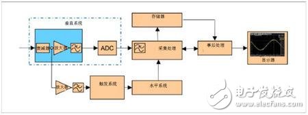
Figure 4: Vertical system
8 grids, 10 grids or some other grids are optional in the selection. For simplicity, 10 grids are usually used: 10 grids are easier to divide than 8 grids. The probe also affects the aspect ratio. Some probes do not attenuate the signal (1X probe), some probes have a 10x attenuation function (10X probe), and some can even achieve 1000x attenuation. Probe problems are discussed below.
The aforementioned input coupling essentially determines the signal transmission from the capture of the signal by the probe to the entire process of passing the cable into the instrument. DC coupling provides 1 M ohm or 50 ohm input coupling impedance.
Selecting 50 ohms of input coupling allows the input signal to be sent directly to the oscilloscope's longitudinal gain amplifier, which allows for the widest bandwidth. Selecting the AC or DC coupling mode (corresponding to the 1M ohm terminal value) places an amplifier in front of the longitudinal gain amplifier, which typically limits the bandwidth to 500 MHz in all cases. The benefit of such high impedance is that it provides inherent high voltage protection. After selecting “Ground†on the front panel, the vertical system will be disconnected and the 0-V point will be displayed on the screen.
Other vertical system related circuits also include a bandwidth limiter that attenuates high frequency signal components when noise is being applied to the displayed waveform. Many oscilloscopes also use a DSP arbitrary equalization filter (anti-aliasing filter) to extend the instrument bandwidth by adjusting the phase and amplitude response of the oscilloscope channel to exceed the original response of the front end. However, these circuits require a sampling rate that satisfies the Nyquist theorem—the sampling rate must be greater than twice the maximum fundamental frequency of the signal. To achieve this, the instrument is typically locked at its maximum sample rate, and the sample rate cannot be reduced to see a longer duration without disabling the filter.
Horizontal systemHorizontal systems are more relevant to signal acquisition than vertical systems, emphasizing sample rate, memory depth, and other performance metrics directly related to data acquisition and conversion.
The time interval between sample points is called the sample interval, and the sample value represents the value stored in the memory for generating the waveform. The time interval between waveform points is called the waveform interval. Since one waveform point may be based on multiple sampling points, the two are related and sometimes may have the same value.
Generally, the oscilloscope's acquisition mode menu is very limited, because one channel can only generate one waveform, and the user can only select one sampling type or one waveform algorithm type. However, some oscilloscopes can display three waveforms in parallel on a single channel, and each waveform can be combined with the sample type and waveform algorithm type. Typical modes include:
• Sampling mode: For each waveform interval, a sample point is used to generate a waveform point.
• High Resolution Mode: For each waveform interval, the average sample point for the waveform interval is displayed.
• Peak Detection Mode: For each waveform interval, the minimum and maximum sample points within the waveform are displayed.
• RMS: Displays the sample point RMS value within the waveform interval. This is proportional to the instantaneous power.
Typical waveform algorithm modes include:
• Envelope mode: Based on the waveform captured by at least two trigger events, the oscilloscope generates a boundary (envelope) to represent the maximum and minimum values ​​of the waveform.
• Average mode: Averages the samples of each waveform interval based on multiple samples.
Trigger system
Trigger is one of the basic units of every digital oscilloscope, used to capture signal events for detailed analysis and to provide a stable repetitive waveform view. The accuracy and flexibility of the trigger system determines how the measurement signal is displayed and analyzed. As mentioned earlier, digital trigger systems offer significant advantages to oscilloscope users in terms of measurement accuracy, acquisition density, and functionality.
ZGAR AZ Vape Pods 5.0S
ZGAR electronic cigarette uses high-tech R&D, food grade disposable pod device and high-quality raw material. All package designs are Original IP. Our designer team is from Hong Kong. We have very high requirements for product quality, flavors taste and packaging design. The E-liquid is imported, materials are food grade, and assembly plant is medical-grade dust-free workshops.
From production to packaging, the whole system of tracking, efficient and orderly process, achieving daily efficient output. WEIKA pays attention to the details of each process control. The first class dust-free production workshop has passed the GMP food and drug production standard certification, ensuring quality and safety. We choose the products with a traceability system, which can not only effectively track and trace all kinds of data, but also ensure good product quality.
We offer best price, high quality Pods, Pods Touch Screen, Empty Pod System, Pod Vape, Disposable Pod device, E-cigar, Vape Pods to all over the world.
Much Better Vaping Experience!


Pods, Vape Pods, Empty Pod System Vape,Disposable Pod Vape Systems
ZGAR INTERNATIONAL(HK)CO., LIMITED , https://www.szdisposable-vape.com