"secret" disassembly of RF receiver chip architecture
In general, in modern radio frequency systems, the signal received by the antenna is very high and has a very small channel bandwidth. If it is considered to directly filter out the desired channel, the Q value of the filter will be very large, and the high frequency circuit has problems in terms of gain, accuracy, and stability. Under the current technical conditions, the signal is directly demodulated at a high frequency band. It is not realistic. Using a mixer to down-convert high-frequency signals, channel filtering, amplification and demodulation at an intermediate frequency can solve the above-mentioned difficulties encountered in high-frequency signal processing, but it introduces another serious problem, namely image frequency interference. : When the frequency of the two signals and the frequency difference of the local oscillator (LO) signal are symmetrically located on both sides of the local oscillator signal on the frequency axis, or their absolute values ​​are the same but the signs are opposite, both signals are mixed. Will be moved to the same IF frequency. If one of them is a useful signal and the other is a noise signal, then the frequency at which the noise signal is located is called the image frequency. This type of interference after mixing is often referred to as image frequency interference.
In order to suppress image interference, a commonly used method is to use a filter to filter out the image frequency components. However, because the filter operates in the high frequency band, the filtering effect depends on the distance between the image frequency and the signal frequency, or depends on the frequency of the intermediate frequency. If the IF frequency is high and the signal frequency is far away from the image frequency, then the image frequency component is greatly suppressed; conversely, if the IF frequency is low, the signal frequency is not far from the image frequency, and the filtering effect is poor. However, on the other hand, since the channel selection is performed in the intermediate frequency band, for the same reason, the higher intermediate frequency requires higher channel selection filters. Therefore, the image frequency suppression and the channel selection form a pair of contradictions, and the selection of the intermediate frequency becomes the key to balancing this contradiction. In some demanding applications, two or three frequency conversions are often used to achieve better trade-offs.
Relying on thoughtful IF frequency selection and high-quality RF (image rejection) and IF (channel selection) filters, a well-designed superheterodyne receiver can achieve high sensitivity, selectivity and dynamic range, and has long been Classic traditional choice. As mentioned before, superheterodyne receivers have great advantages in suppressing image frequency interference, sensitivity, and selectivity, and there are no DC drift and signal leakage in multi-level conversion, but there are also high costs and high IR filters. Requirements, need for low noise amplifier (LNA) and mixer (Mixer) and 50W good matching and other shortcomings, and the image frequency suppression filter and channel selection filter is usually not suitable for monolithic integration.
The subsequent Zero IF structure, as shown in Figure 1, does not require suppression filters and reduces intermodulation modulation, making it more suitable for monolithic integration. However, there are also drawbacks of dc offset and signal leakage, and high-frequency, phase-noise frequency synthesizers are also required, which brings certain difficulties to the circuit design. Similarly to the zero IF, the Low IF structure is also suitable for integration, and the structure thereof is shown in FIG. 2 (both of which are exemplified by the IEEE 802.15.4 protocol in the 2.4 GHz band). But what needs attention is the suppression of the in-band image frequency signal. Usually requires a 70dB image rejection ratio, but on-chip integration can often only reach 40dB or less.
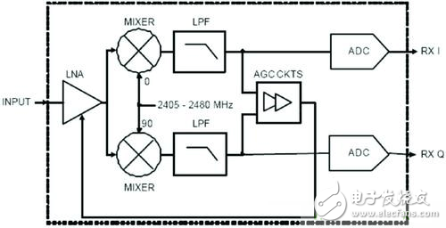
Figure 1 Zero-IF receiver structure; low-IF receiver structure
Other receiving structures include broadband-dual IF receivers, sampling receivers, and digital IF receivers. The wideband-dual-IF receiver structure has the advantages of easy integration, low cost, low power consumption, and the disadvantages thereof are the flicker noise effect, obvious second-order intermodulation distortion, and the problem of radio frequency intermediate frequency crosstalk. Subsampling receivers and digital IF receivers have high requirements for analog-to-digital converters (ADCs) such as ADCs with sufficiently high dynamic range, band-pass Σ-Δ ADCs, etc. The on-delta ADC has a larger design difficulty.
For the reasons stated above, the design of radio frequency chips using zero-IF and low-IF schemes is common nowadays, and they are also two schemes that RF receivers usually need to carefully evaluate. The zero-IF uses IQ demodulation to extract information such as phase and quadrature components, which are digitized and processed by the ADC. Low-IF uses a typical frequency-limited discriminator to extract signals from the modulated carrier.
The low IF structure avoids the automatic gain control (AGC) circuit and has a faster response to the channel signal quality, thereby reducing the complexity of the receiver and associated circuitry. Discriminators and other circuits are easy to design, do not require carrier synchronization and high current, and occupy less chip area. However, compared to the zero-IF structure using coherent demodulation, the low-IF structure has a 3 dB loss in sensitivity. And usually the low IF structure requires a channel filter to obtain an effective carrier frequency, reducing the effects of noise, adjacent channel interference, and the like. If the frequency width of the signal defined by the protocol used by the radio frequency system and the requirement for adjacent channel selection are loose, the requirements for the filter are relatively low. The low IF structure also requires the image rejection mixer to reduce image interference issues.
For low-chip-rate protocols, such as 2M Chips/s, the required FM width is approximately 2 MHz. If the IF is too low and the relative bandwidth of the channel filter is too high, then the filter is also difficult to implement, and it is difficult to filter out the IF signal, and the difficulty is passed on to the baseband digital filter. In contrast, too high frequency of the IF filter requires the amplifier's bandwidth to be large enough.
Compared to low IF, the zero-IF architecture does not require the LO to change frequency between receive and radiation modes, which reduces the difficulty of designing the frequency synthesizer. The zero-IF structure also does not require an image rejection mixer because the zero-IF structure does not produce image frequencies. Compared to the design of an equal bandwidth mid-band filter, the zero-IF architecture requires only a simpler low-pass filter to determine the I- and Q-output SNR. The zero-IF structure can achieve the best demodulation effect in filter matching and synchronous detection techniques.
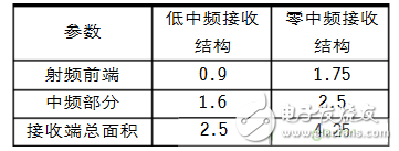
However, zero-IF has its own shortcomings compared to low-IF technology. For example, it needs the AGC and DC offset cancellation circuit after the mixer, and since the signals are divided into I and Q channels, two analog-to-digital converters (ADCs) and a common ADC are required to perform signal modeling. Number conversion. An IQ analog interface is required between the IQ two-way baseband chip or the integrated baseband circuit. An important design difficulty in the IQ structure is the IQ balance problem. The imbalance of the amplitude and phase between the two IQ channels will cause the IQ picture to be superimposed on the useful signal, which will degrade the EVM performance. Therefore, the zero-IF structure sometimes requires additional circuitry to isolate the baseband chip for synchronous demodulation. Table 1 gives the area comparison of two designs of an IEEE 802.15.4 RF receiver in a 0.18 mm process.
Through the above description, the advantages and disadvantages of several common receiving structures are briefly compared. Choosing the structure that best fits the protocol also includes considerations of power consumption, overall matching, image elimination, flicker noise, and quality noise. Low power consumption considerations include direct conversion, low pass SD ADC, and quadrature band pass SD ADC. For different protocols, their flicker noise, code rate, and so on are all different and need to be simulated before reaching a conclusion.
In short, the structure design of the receiver is very important. It cannot be simply considered which structure is “good†and which structure is “badâ€. Instead, it requires careful analysis of the protocol requirements, simulation based on relevant parameters, and the final decision will involve many aspects. Eclectic considerations.
Laptop power adapter charger for Asus:
Laptop Model
Power Adapter
K42F K42JB K42JK K42JR K42JV K52f A52f A42 X52f A52 A52f A52J
19v 3.42a, 5525
K60IJ K50IJ K50I K60I
19v 4.74a, 5525
Our service:
Stable output and high charging efficiency.
Elegant outlook design as original one, touch smoothly and comfortable.
Original charger is good, but as a replacement, our product has more reasonable price when your original charger is broken.
And, the market of the replacement adapters becomes bigger and bigger. People would rather buy a copy one then the original because of the price.
But at the same time, people worry about that they will buy something defective. So the problem comes, how to buy a good quality one with a good price?
As a professional power adapter manufacturer, we have excellent R&D team, skilled staffs and responsible after-sale service. All your benefits can be under protected after you buy products for our company.
Our certificates :ISO9001:2008 & ISO14001:2004 , CCC , CE , FCC , ROHS.
All our products has 1 year warranty. In other words, if you get the dad products which are not damaged physically from us in one year, we will replace you the new one or the whole bulk order.
Asus Adapter,Adapter For Asus,Laptop Adapter For Asus ,Power Supply For Asus
Shenzhen Waweis Technology Co., Ltd. , https://www.laptopsasdapter.com