Self-made small power amplifier power amplifier circuit principle
The amplifier is regarded as an aristocratic machine. The expensive "export cow" alone is enough for many friends to talk about "biliary" discoloration. In fact, don't "burn a cow" can still make a gallbladder fever.
Although the material used in this machine is not elegant, its frequency response range can easily reach from around 100~18000HZ. We know that most people have a hearing range of only 30~15000HZ, so the upper limit frequency is enough. So how is the lower limit frequency satisfied? Use an active subwoofer, which not only achieves the downward extension of the audio frequency, but also compensates for the lack of sound of the small power amplifier.
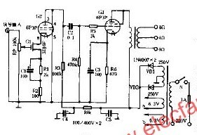
As shown in the figure, the low-power amplifier uses the domestic junction FET 3DJ6F and the domestic 6P3P as the input machine for the low-power amplifier. Both the sound quality and the dynamic range are better than those of the 6N1.
That is to use the ordinary output transformer, the sound quality is not comparable to the ordinary large-screen color TV audio. Its input can be directly connected to CD or VCD, SVCD, CVD output.
The resistors used in this stage are metal film resistors, capacitor C2 can use CBB capacitors, C1 and C3 are aluminum capacitors, the connection line is silver-plated wire or thick single-strand copper wire, and the output transformer can be used with ordinary fixed resistance or constant pressure type. Line-to-line output transformers, conditional replacement of a pair of "output cattle" effect is better, the grounding inside the machine should be concentrated to a little shell, you can use galvanized or aluminum plate to make.
- The Description of wifi Antenna
-
When selecting the antenna, it is necessary to pay attention to whether the connector of the antenna matches the connector of the connected device. Generally, SMA and TNC are used for WIFI
To use on the router, but on the 2.4 G wireless monitoring equipment fittings, if match, also can achieve the enhancement effect of the wireless signal transmission Magnetic antenna base, can suck on metal surfaces, makes the antenna signal is stronger Plug and play, without any additional conditions, but the antenna gain and directional property management are key points to consider. -
Magnetic antenna bases offer a convenient solution for mounting the antenna on metal surfaces. By utilizing the magnetic properties, these bases allow for easy and secure installation without the need for drilling holes or using screws. This feature not only simplifies the installation process but also potentially strengthens the antenna signal by providing a stable platform with optimal orientation for signal transmission.
- The first standard WIFI antenna products were made by LTCC process, because of its width and general performance. Abroad, Airgain has launched a standard antenna with high temperature resistance and plastic seal, which is used in laptop computers, and a series of WiFi antennas with magnetic dielectric in mobile phones have been launched in China.
- The Picture of wifi Antenna
-

Wifi Internal Antenna,Wifi Antenna for PC,Wifi Antenna for Router,Wfi Antenna outdoor,Wifi Antenna Indoor
Yetnorson Antenna Co., Ltd. , https://www.yetnorson.com