Control the servo with Siemens 1217C PLC
Yaskawa's servo drive only supports the communication protocol MECHATROLINK-II of Yaskawa Control System. The method currently used with other manufacturers' PLCs can only be controlled by pulse sequences. In this example, the Siemens 1217C PLC is used to control the servo.
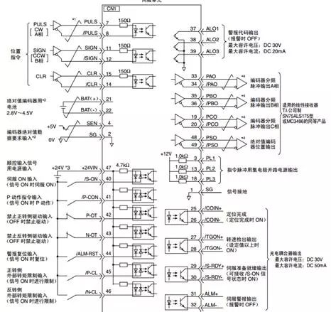
On the wiring, Yaskawa drives use different control methods, and the wiring is slightly different. We take the location mode as an example. The hardware wiring schematic is as follows:
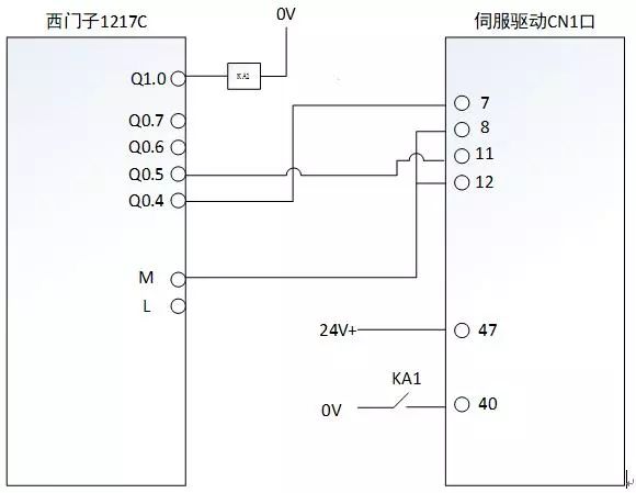
The wiring diagram of the 1217C is as follows:
l Software configuration
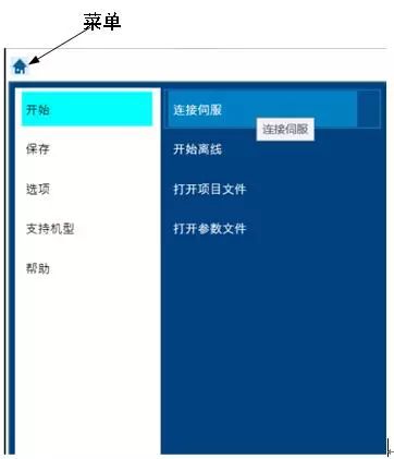
Yaskawa servo drive debugging can use SigmaWin+, the software can be downloaded from the official website. After installation, the interface is opened as follows:
Click the "Menu" button and select Connect Servo in the beginning.
The system will automatically search for the Yaskawa servo drive connected to the computer. As shown below:
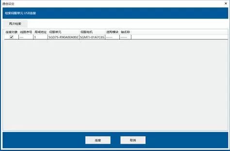
The automatic search function can find the connected servo and motor without having to configure some relevant parameters of the motor. Click "Connect." The connected drive can be seen from the figure below.
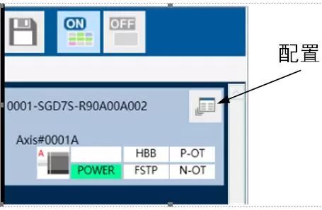
Click Configure to open the drive parameter configuration interface. as follows:

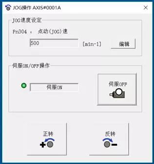
We can first jog the motor to see if the wiring is correct.
Next configure the parameters of the drive. Open the parameter edit table and set the direction of rotation:
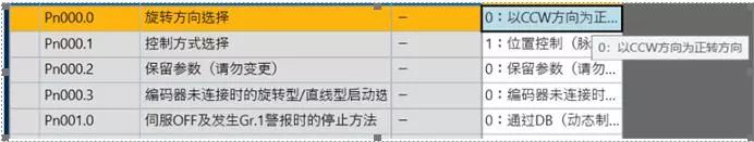
Set the control mode to position control:

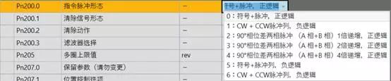
Set some parameters of position control, such as command pulse shape, filter selection, etc. The filter is selected according to the controller type.

Then need to set the input and output signal distribution, allocation mode selection 1;
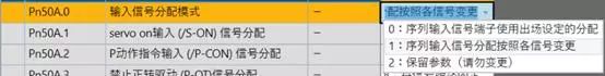
(/S-ON) Signal assignment selection ON (closed) is valid;

Prohibit forward and reverse drive assignments, and choose to always fix the signal to positive and negative drive.

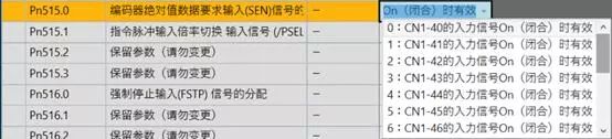
Because this motor is an absolute encoder, the SEN terminal needs to be set to ON. The default is 5V input is valid. There is no 5V power supply here, so it is effective to modify the CN1-40 terminal ON.
After setting these parameters, the motor can be controlled from the PLC.
The last item is to change the electronic gear ratio so that the PLC program matches the actual number of motor runs. This motor encoder is a 24-bit resolution encoder. Therefore, the motor receives 16777216 pulses for one revolution. The Siemens process axis sets 1000 pulses to one revolution, so the electronic gear ratio is 16777216/1000.
Focusing on the development and production of Wireless Charging products that make life easier.
Supply various wireless charger including multifunctional Wireless Charger, Car Wireless Charger, Magnetic Wireless Chargin, Wireless Charging Mouse Pad, etc.
We help 200+ customers create custom wireless charging products design for various industries.
Manufacturing high quality products for customers according to international standards, such as CE ROHS FCC REACH UL SGS BQB etc.
Wireless Charging Pad,Wireless Phone Charger,Wireless Car Charger,Bluetooth Charger
TOPNOTCH INTERNATIONAL GROUP LIMITED , https://www.itopnoobluetoothes.com