Frequency divider structure and wiring method
The frequency divider refers to distinguish the sound signals of different frequency bands, respectively amplify them, and then send them to the speakers of the corresponding frequency bands for replay. When reproducing high-quality sound, electronic frequency division processing is required.
The frequency divider is a circuit device in the speaker, used to separate the input analog audio signal into different parts such as treble, midrange and bass, and then sent to the corresponding high, middle and woofer units for playback. The reason for this is that no single speaker can perfectly reproduce the sound in all frequency bands.
The crossover is the "brain" in the speaker, which is crucial to the sound quality. The music signal output by the power amplifier must be processed by the filter element in the frequency divider to let the signal of a specific frequency of each unit pass. It is necessary to design the frequency divider of the speaker scientifically, reasonably and rigorously to effectively modify the different characteristics of the speaker unit and optimize the combination so that each unit can develop its strengths and avoid its shortcomings. Only smooth, accurate image phase can make the high, middle, and low-pitched music layer have clear, coherent, bright, comfortable, wide, and natural sound quality effects.
In a speaker system, people call the cabinet, crossover circuit, and speaker unit as the three major parts of the speaker system, and the crossover is the "brain" in the speaker. Can the crossover circuit restore the speaker system with high quality? Electroacoustic signals play an extremely important role. Especially in the middle and high frequency parts, the role played by the frequency dividing circuit is more obvious.
Circuit to connect the tweeter: let the current flow through the capacitor first, stop the low frequency, let the high frequency pass, and the speaker is connected in parallel with a coil to make the coil produce a negative voltage, then this voltage is just a voltage compensation for the tweeter, so it can The sound current is approximately realistically restored.
Connect the woofer circuit: the current flows through the coil first, so that the high frequency part is blocked, and the low frequency band passes smoothly because the coil basically has no obstruction. Similarly, the woofer is connected in parallel with a capacitor, which uses the capacitor to generate a Voltage to compensate for the lost voltage is the same as the tweeter end.
It can be seen that the characteristics of the capacitors and coils fully utilized by the frequency divider reach frequency division. However, the coils and capacitors still consume voltage in the frequency bands hindered by each other, so the circuit divider will lose a certain amount of sound, and there are many compensation measures. Electronic frequency division solves this problem. When the sound is input to the power amplifier, it is divided first, and then a special amplifier circuit is used to amplify the different frequency bands. In this way, the sound distortion is small and the reproduction is realistic. But the circuit is complicated and expensive.
Crossover wiring method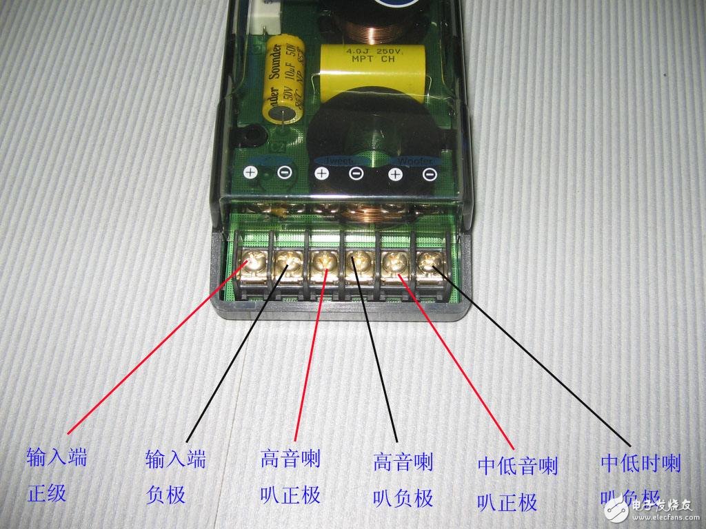
The speaker crossover cable is generally divided into signal input and signal output (connected to high, medium and low speaker units). The connection method of the speaker crossover is very critical. If the connection is reversed, the sound quality will be far from the design and debugging, or completely opposite. The wrong connection sometimes burns the unit.
Some people think that the speaker crossover connection should follow the blue wire to the treble red wire to the woofer unit, but we can't follow the steps.
If you are unsure of the speaker crossover connection, you can try the following methods:
First, the crossover should be removed to view the silk screen near the wiring hole on the PCB circuit board. Generally, IN + / IN- or input + / input- will be marked near the input line hole, and low + / low-, treble will be marked near the line hole of the woofer unit. Hi + / hi- will be marked near the line hole of the unit;
Secondly, the general experience is that the blue wire is connected to the treble red wire to the woofer unit, the black wire is the ground wire, and the signal input wire is generally four red and black parallel wires;
In addition, you can check the connection terminals of the connection line. The positive and negative terminal plugs of the general speaker unit are one large and one small. The large plug of the treble will be smaller than the lower sound speaker unit. The signal input terminals are generally 4 large Insert.
Car divider connection
There are 8 terminals on the general vehicle frequency divider.
The input English marked by the crossover is "INPUT"
The terminal connected to the subwoofer is "WOOFER"
The terminal connected to the bass is "BASS"
The terminal connected to the midrange is "MEDIAN"
The terminal connected to the treble is "TREBLE"
Among them, there are two terminals for INPUT, two terminals for WOOFER, and four terminals for TREBLE, one is a negative electrode, and the other is a tweeter's gain enhancement and attenuation connectors, which are + 3db, 0db, and -3db, respectively.
The connection method is: the input signal from the host is connected to INPUT, the subwoofer is connected to WOOFER, the bass is connected to BASS, and the treble is connected to TREBLE.
Electronic crossover
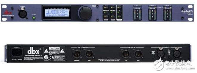
The front panel of the electronic crossover introduces the function of each function key, button and interface.
(1) INPUTGAIN: input gain. Input signal level adjustment is generally placed at the rib B position.
(2) LFDELAY: bass delay. Delay O-2ms (max 60cm) for bass.
(3) LF / HFGAIN: low frequency / high frequency gain. Adjust the level of low frequency band and high frequency band.
(4) MUTE: mute. Block signals in a certain frequency band.
(5) x-0VERPREQ: crossover frequency (crossover point). When dividing by two, there is only one dividing point; when dividing by three, there are two dividing points.
(6) RANGE: frequency range-o frequency range is selected between 90-900Hz or 900Hz-9kHz.
(7) MODE: frequency division mode. Choice of two-channel two-way crossover or mono three-way crossover.
(8) MONOBASS: mono bass. In the two-channel stereo mode, you can select mono bass output.
(9) CDEQ: constant pointing horn equalization. In the case of using a constant pointing horn (patent of the American EV company), the high frequency band characteristics can be made better.
(10) LIMITER: Limit button. The output signal gain limit adjustment is used to limit the excessive signal and protect the power amplifier speaker.
(11) THRESHOLD: threshold selection key. Choose the limit threshold range, there are two choices of -6dB and + 18dBu.
The back panel of the electronic crossover is generally based on various interfaces. The functions of each interface and function keys are described below:
(1) FUSE: insurance and power socket
(2) SERIALNUMBER: product series number
(3) HIGH / MID / LOWOUTPUT: high frequency / intermediate frequency / low frequency output interface. When the two-channel two-way output, the high frequency and low frequency are output according to the frequency band above the interface; when the single-channel three-way frequency, the high frequency, mid frequency and low frequency are output according to the frequency band below the interface.
(4) POLARITY: Polarity (phase) key, which can be used for reverse phase adjustment.
(5) INPUT: signal input interface. Input a full-frequency signal from this interface, and input the signal from the left channel in mono-way three-way frequency mode.
Diy Breadboard Kit,Breadboard And Jumper Wire Kit,Large Breadboard Kit,Breadboard Prototyping Kit
Cixi Zhongyi Electronics Factory , https://www.cx-zhongyi.com