Hardware Circuit Design of UAV Remote Sensing Platform Control System
Compared with satellite and manned aerial aircraft remote sensing platforms, drones are characterized by low cost and high flexibility. In order to meet scientific remote sensing experiments, complete remote sensing tasks, coordinate multi-component work in drone electronic pods, and control the attitude of remote sensing image sensors, the system uses AT89S52 as the main control chip to extend the multi-channel serial port and USB interface to realize the system and peripheral devices. The communication is designed with the camera drive module and the three-degree-of-freedom stepper motor drive module. The UAV aerial remote sensing experiment proves that the system can meet the requirements of remote sensing experiments.
USB interface expansion circuit design
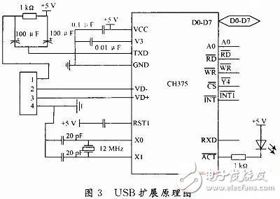
The USB port expansion is implemented by the CH375 chip. CH375 is a universal interface chip for the USB bus produced by Nanjing Yuheng Co., Ltd. Its main features are cheap price, convenient interface and high reliability. Support USB-HOST host mode and USB-DEVICE/SLAVE device mode. The USB host mode of the CH375 supports commonly used USB full-speed devices. The external MCU needs to write a firmware program to communicate with the USB device according to the corresponding USB protocol. However, for commonly used USB storage devices, the built-in firmware of the CH375 can automatically handle the dedicated communication protocol of Mass-Storage mass storage devices. Under normal circumstances, external microcontrollers do not need to write firmware programs. It is possible to directly read and write data in a USB storage device. There are two ways to communicate between CH375 and MCU: parallel mode and serial mode. The schematic diagram of the USB expansion circuit is shown in Figure 3. The CH375 chip is set to the built-in firmware mode using a 12 MHz crystal. The P0 port of the MCU is connected to D0~D7 of CH375 as the data bus, and the decoder output ![]() With CH375
With CH375 ![]() The chip is connected to the chip, and the MCU A0 is connected to the A0 of the CH375, and the address or data input and output of the CH375 can be selected. When A0 is high, the transmission of D0~D7 is the address, and when it is low, the data is transmitted. P3.6 and P3.7 control the read and write operations of CH375. CH375
The chip is connected to the chip, and the MCU A0 is connected to the A0 of the CH375, and the address or data input and output of the CH375 can be selected. When A0 is high, the transmission of D0~D7 is the address, and when it is low, the data is transmitted. P3.6 and P3.7 control the read and write operations of CH375. CH375 ![]() Single chip
Single chip ![]() At the input end, when there is data input through the USB port, an interrupt signal is generated to notify the microcontroller to perform data processing. After the CH375 chip is initialized and successfully connected to the host, the indicator light is on.
At the input end, when there is data input through the USB port, an interrupt signal is generated to notify the microcontroller to perform data processing. After the CH375 chip is initialized and successfully connected to the host, the indicator light is on.
Stepper motor drive circuit
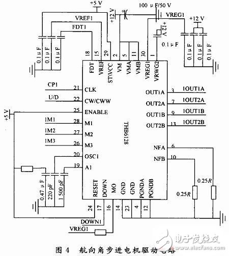
The stable pan/tilt control is a three-degree-of-freedom stepper motor control, that is, controlling the pitch angle, the roll angle and the heading angle of the remote sensing sensor to maintain the stable pan/tilt in a horizontal (or vertical) state. The stepper motor drive is realized by the THB6128 chip. The single-chip microcomputer only needs to output the stepping motor running direction and pulse signal to achieve the purpose of controlling the stepping motor.
THB6128 is a high-subdivision two-phase hybrid stepping motor driver dedicated chip. By outputting control signals through a single-chip microcomputer, a high-performance, multi-subdivided drive circuit can be designed. It features dual full-bridge MOSFET drive, low on-resistance Ron=0.55 Ω, maximum withstand voltage of 36 V, high current of 2.2 A (peak), multiple subdivision options, up to 128 subdivisions, with Automatic semi-flow locking function, fast decay, slow decay, hybrid attenuation, 3 attenuation modes, built-in temperature protection and overcurrent protection. Figure 4 shows the stepping motor drive circuit of the heading angle. The pitch angle and roll angle stepper motor drive are the same. In the figure, CP1 and U/D are respectively the driving pulse and motor running direction control signal given by the single chip microcomputer. M1, M2, and M3 are motor drive subdivision number selection signal inputs, which are controlled by the dial switch. FDT1 and VREG1 select the voltage and current control voltage inputs for the attenuation mode, respectively. When it is 3.5 V, it is slow decay mode; when it is mixed attenuation mode; when FDT1 is 0.8 V, it is fast decay mode. Adjust the VREG1 terminal voltage to set the stepper motor drive current value.
CCD/camera drive circuit design
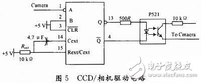
The CCD/camera drive is implemented by a monostable flip-flop 74LS221 and an optocoupler P521. The 74LS221 can be either a falling edge trigger or a rising edge trigger, and both can disable the output. The pulse width of the output is obtained by internal compensation without external voltage and stability. In most applications, the pulse width is determined only by external timing components. The CCD/camera drive circuit is shown in Figure 5. The one-shot of the illustrated parameter has a high-level duration of approximately 33 ms. The charge time constant RC of the circuit can be changed to adjust the length of the steady-state time according to the actual exposure time of the camera. In the figure, Camera is the P3.5 port of the single-chip microcomputer. When it is the falling edge, it triggers the one-shot trigger output high level. This high level acts on the diode terminal of the optocoupler P521, thereby triggering the triode end conduction. Trigger the camera shutter. The output of P521 is connected in series with a 10kΩ resistor to prevent the current from being too large and causing damage to the camera.
The data storage module is realized by AT24C512. The MCU P3.0 and P3.1 ports are respectively connected with the SCL and SDL ports of AT24C512, and the pull-up resistors are connected, and the I2C bus is extended to 64 KB E2PROM data memory. The SRAM extension is implemented by the IDT6116SA chip, which extends 2 KB to cache temporary data during microcontroller calculations. The system input voltage is 12 V DC, and the power module uses a series of 7805 and 7805 three-terminal regulators to reduce the voltage drop across the monolithic regulator and obtain a smooth +5 V voltage. |
The experiment proves that the system can better meet the requirements of the airborne operation control of the UAV airborne remote sensing platform, coordinate the work of each component of the electronic pod, control the attitude of the camera, and downlink the onboard operation data in real time. There are fewer O ports, and the expansion of the USB interface solves the problem that many notebook computers do not have a COM port at present, and can process the photo information data in the operating system in time in the field experiment. The MCU still has more resources to use, which can facilitate the system upgrade, but it is also limited by the microprocessor data processing capability.
Can you boost your WiFi signal with outdoor 4G CPE?
When you travel or go to some remote areas, you may be annoyed by poor reception. Is there any way to get a strong WiFi router signal outdoors in a 4G LTE network? Very good, outdoor 4G CPE router would be a good choice!
What is an outdoor 4G CPE router?
An outdoor 4G CPE router differs from a Wifi-only router in that it needs to be connected to a fiber optic network. The 4G CPE WiFi router can pick up the carrier's 4G LTE network signal and convert it into broadband and Wi-Fi. Just plug in your SIM card with your data plan and enjoy a stable and reliable WiFi signal with family and friends. This Outdoor CPE can be used in harsh environments. If you install your router outside or near a window in an area with a weak 4G signal, your device can receive a better 4G signal.
Second, what are the characteristics of outdoor 4G CPE router?
1. Better network for ODU and IDU
4G CPE outdoor routers include an outdoor unit (ODU) and an indoor unit (IDU). Help your device receive the best outdoor cellular signal through the ODU, and connect to the indoor WiFi router through the network cable to experience better network speed. As shown in the figure below, an outdoor LTE CPE (ODU) is installed outdoors and connected to an indoor Wi-Fi router (IDU) via a network cable. The entire 4G device is powered by POE. This data will be transmitted over the same Ethernet cable, eliminating the need to connect the ODU to a power outlet.
2. High-speed multi-user available
The outdoor 4G CPE features a built-in 4G LTE modem and a 5dBi high-gain antenna. LTE CAT4, download speeds up to 150Mbps, WiFi speeds up to 300Mbps, can connect 32 users at the same time. The high-gain antenna of the outdoor 4G CPE router enables it to have higher power and stronger signal transmission and reception capabilities than mobile phones. Therefore, the CPE router can receive the signal. If your phone can't receive a signal in some areas. Sometimes you also use your phone as a hotspot to share Internet access with your friends, right? Similarly, this 4G LTE CPE router allows 32 users to connect to WiFi at the same time, allowing more users to connect and receive a better signal than a phone sharing hotspot. In addition, the IDU has four Lan ports and can be connected to the device through network cables, which is also a backup mode of the Internet.
3. Excellent outdoor performance and design
On the one hand, outdoor LTE CPE is waterproof, UV resistant and corrosion resistant. It can be used at -20℃~60℃ operating temperature. Therefore, it is ideal for outdoor deployment. On the other hand, there are a variety of installation methods. CPE can be mounted on Windows or walls by mounting brackets. It is also possible to attach it to the antenna mast. In addition, the signal strength is displayed through the LED indicator to facilitate users to find the best location to get a better 4G signal.
4. Support different frequency bands
Outdoor 4G CPE supports a variety of frequency bands, including LTE-FDD, LTE-TDD, 3G WCDMA, and 2G GSM network bands. Meet the needs of different frequency bands in different regions and make full use of network resources.
5. Convenient management of CPE
Start the Web browser to log in to the Web management page. You can configure and manage the CPE easily. The web management system supports Linux. Provides functions such as WebUI management, Telnet, SSH terminal system status monitoring, NTP client, synchronization between devices and the system clock network, and configuration file import and export.
6. Applicable to various application scenarios
CPE is designed to provide ISP or operator with 4G LTE outdoor wifi router to facilitate network connection, whether at home, or in enterprises and remote areas, to bring users a wonderful network experience.
All in all, an outdoor 4G CPE router is an excellent choice for connecting to the Internet in remote areas and places where the signal is weak, the wired network is unreliable, or there is a lack of reliable WiFi. It's worth deploying outdoor CPE in rural, coastal, boat, caravan, campsite and remote areas to enjoy the best network speeds and outdoor activities! It can even reduce complex cabling deployments for home networks without the need to install a wired fiber network.
4G Outdoor Cpe,4G Lte Outdoor Cpe Router,4G Lte Outdoor Cpe,Outdoor 4G Lte Cpe Router
Shenzhen MovingComm Technology Co., Ltd. , https://www.mcrouters.com