In-depth analysis of the application of S7-300 PLC in substation
Application of S7-300 PLC in Substation
There are more than 150 substations in an oil field, which are responsible for the electricity consumption of the residents in the entire oilfield, community and living areas of the oilfield. The safe operation of the oilfield power grid plays a vital role in ensuring the continuous increase of crude oil production and the residents' well-being.
The AEUD-WIII fully automatic intelligent maintenance-free DC screen in the oilfield substation adopts modular design and digital control, and has a high degree of intelligence. The DC power supply has advanced system monitoring functions, focusing on battery online management, grounding line selection, "four remote" communication, alarm display and accident recalling functions, which makes the system more secure and reliable.
This series of fully automatic intelligent maintenance-free DC screen adopts the OP170B human-machine interface produced by SEIMENS. The monitoring module has the advantages of compact structure, high display resolution, high reliability and long life. Through the man-machine interface, the rectifier module can be started, the charging status display, the alarm information, the manual battery inspection, the insulation monitoring, the ground selection, the alarm test, the alarm reset and other DC screen operations can be completed, and the schematic diagram of the DC screen can be displayed. And various operating parameters and various fault information. The control module uses S7-300 series modules to collect and output digital and analog signals.
Hardware system composition
1.PLC configuration
The PLC of the substation DC monitoring system uses Siemens S7-300 PLC. According to the system requirements, the overall configuration of the PLC is as follows:
1 Central Processing Module (CPU): CPU 314 is selected.
2 digital input module (DI): select SM321, a total of 1 block (16 points / block), processing 4 input signals.
3 digital output module (DO): select SM322, a total of 4 blocks (16 points / block), processing 56 input signals.
4 Analog input module (AI): Select SM331, a total of 1 block (8 points / block), processing 8 input signals.
5 analog input and output module (AI): select SM334, a total of 1 block (4 points in and 2 points out / block), handle 2 point input and 2 point output signal.
2. Operation screen configuration
The operation panel uses two OP170Bs, one installed in the control cabinet and one installed in the monitoring center.
Monitoring system software
The software of the substation DC monitoring system mainly has two parts: the display unit and the software unit.
Display unit
The operation screen adopts industrial-level man-machine interface, which mainly completes tasks such as DC system operation monitoring, fault alarm, recording and troubleshooting prompts, parameter setting, analog keyboard operation, data recording processing, and accumulated running time control.
The display unit includes a main screen, a battery inspection screen, a battery pack voltage recording screen, an insulation monitor, a current alarm screen, a history alarm screen, and a cumulative operation screen.
2. Control software unit (only some functional software is given)
The software unit consists of system clock reading, rectifier control, battery inspection, insulation monitoring, ground selection, current limiting resistor control, cumulative running time, current alarm processing, historical alarm information processing, and alarm test.
1) Rectifier control.
Given delay
A "F1_k1"
AN "F1_k2"
= "DO_k1"
Main charger given
A "DI_k1"
JNB _001
CALL FB21, DB21
_001: NOP 0
Main charger given reset
AN "DI_k1"
AN "DI_k2"
= L0.0
A L0.0
BLD 102
S “float_chargeâ€
A L0.0
JNB _004
L 0
T “ug_hm0â€
_004: NOP 0
A L0.0
JNB _005
L 0
T “ug_hm1â€
_005: NOP 0
A L0.0
JNB _006
L 0
T DB66.DBD580
_006: NOP 0
Main float conversion
A (
O "DI_k1"
O "DI_k2"
)
JNB _003
CALL FB20, DB20
_003: NOP 0
2) Inspection: It is possible to perform battery inspection (partial program) automatically (timely every day) and manually.
10 points per day automatic battery inspection
A (
L MW22
L 10
==I
)
FP M15.2
AN "scan_end"
S "scan_start"
Press the panel battery patrol button to manually perform battery inspection
A (
A "F3_bat_scan"
FP M15.3
O(
A "F3_bat_scan"
FN M15.4
)
)
AN "scan_end"
S "scan_start"
Battery inspection begins
A "scan_start"
JNB _001
CALL FB23, DB23
_001: NOP 0
The battery inspection starts and the screen goes to the battery inspection screen.
A "scan_start"
FP M17.4
JNB _002
L 2
T MW102
_002: NOP 0
Battery inspection is over, reset battery pack serial number
L MW186
L 18
==I
= L0.0
A L0.0
JNB _003
L 0
T MW116
_003: NOP 0
A L0.0
JNB _004
L DB65.DBW100
T MW118
_004: NOP 0
A L0.0
BLD 102
L S5T#2S
SD T51
Battery inspection is over, set battery inspection flag
A T51
= L0.0
A L0.0
JNB _005
L 0
T MW186
_005: NOP 0
A L0.0
BLD 102
S "scan_end"
After the battery inspection is over, it is judged by the undervoltage
A "scan_end"
JNB _006
CALL FB24, DB24
_006: NOP 0
3) Insulation monitoring and grounding line selection: It is capable of automatic (daily timing) and manual insulation monitoring and grounding line selection (partial procedures).
Determine if the system clock is 9 points, and if so, start the automatic execution of the insulation monitoring function.
A (
L MW22
L 9
==I
)
FP M15.5
S "auto_gnd_chk"
According to the insulation monitoring Hall voltage sample value and the set value, determine whether there is unbalanced grounding, if it occurs, start
AN “gnd_chkâ€
= L2.0
A L2.0
A (
L MW148
L MW122
>I
)
FP M15.6
S “en_unbalanceâ€
A L2.0
A (
L MW148
L MW122
<=I
)
FP M15.7
R “en_unbalanceâ€
Insulation monitoring is started when any of the three conditions for the insulation monitoring start is met.
A (
O "auto_gnd_chk"
O(
A "en_unbalance"
FP M16.1
)
O(
A "en_unbalance"
FN M16.2
)
O(
A "F4_gnd_chk"
FP M16.3
)
O(
A "F4_gnd_chk"
FN M16.4
))
AN “gnd_chkâ€
S "en_chk"
Insulation monitoring screen when performing insulation monitoring
A "en_chk"
FP M17.5
JNB _001
L 4
T MW102
_001: NOP 0
After the monitoring is completed, the monitoring is enabled to reset
A M17.0
R “en_chkâ€
R “gnd_chkâ€
After the monitoring is completed, the resistance value to the ground, the voltage value record and the alarm are issued.
A M17.0
JNB _009
CALL FB25, DB25
_009: NOP 0
4) Current alarm and historical alarm information processing (program omitted).
Faults are classified into two levels: they are classified into general faults and fatal faults.
General faults include:
When such a fault occurs, only the sound and light alarm is given, and the current operation is not interrupted. According to various faults generated in the system, the relevant fault sound and light alarms and records are implemented. At this moment, the display enters the fault alarm screen, displaying the fault content, nature, time, and pressing ACK to cancel the audible alarm, but the fault display still exists until the fault is cancelled.
Fatal faults include:
When such a fault occurs, all control outputs will be disabled, sound and light alarms will be displayed, and the fault type, content, and time will be displayed on the display. Only after troubleshooting, the system resumes normal operation after pressing the manual reset button.
Ordinary fault indication (K8)
L MW84
L 1
==I
= M8.4
Fatal fault indication (K9)
L MW84
L 2
==I
= M8.7
(5) Display screen and LED light indication
Main charger running indicator (F1)
A "DI_k1"
= M6.0
= M6.1
Main charger DC output fault flashing alarm control (fault)
A (
O(
L DB65.DBW202
L 1
==I
)
O(
L DB65.DBW204
L 1
==I
)
)
JNB _00f
L 1
T MW52
_00f: NOP 0
Battery charge status display control (main charge)
A "DI_bat"
AN “float_chargeâ€
JNB _019
L 1
T MW68
_019: NOP 0
Battery charge status display control (floating charge)
A "DI_bat"
A “float_chargeâ€
JNB _01a
L 2
T MW68
_01a: NOP 0
summary
The oil field substation DC monitoring system has been improved from S7-200 system to S7-300 system since 2001. The normal operation proves that the whole system is advanced and reasonable in design, simple in operation, high in reliability, and meets the requirements of users. It has become a promotion project.
Application of S7-300 PLC in Circuit Breaker Limit Current Test System
The circuit breaker limit current test system communicates with the CP 340 (RS-232C) module of the S7-300 through the industrial PC serial port, enabling real-time monitoring of the system.
Limit current test system introduction
A circuit breaker is a switching device that can switch on and off normal load current, overload current, and short circuit current. In order to calibrate the limit current of the circuit breaker to meet the factory requirements, each product must be measured by the limit current test system. The following is the application of IPC in SZ high-tech zone electrical equipment manufacturing enterprise combined with S7-300 PLC.
1. The framework of the test system
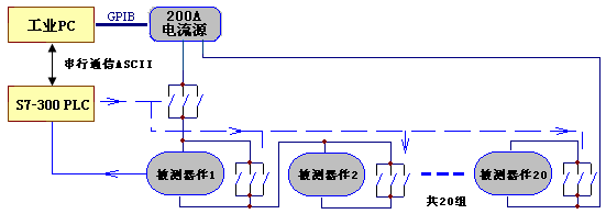
The main control of the system is undertaken by IPC. It is responsible for the parameter setting of the test, the model selection of the product, and the record analysis of the test information. The S7-300 communicates with the IPC in ASCII mode, receives the IPC command, and controls the contactor of the system. Execution equipment such as solid state relays, and returning the test information to the IPC. In order to provide a working environment for the circuit breaker test, the current source power supply mode is adopted in the system.
Consider improving the efficiency of the test. The system is designed to provide 20 test environments. 20 sets of tested equipment can be tested in series at the same time. Once one or some of them are tripped during the test, the bypass contactor and bypass are tested. The solid state relay (not shown) is turned on immediately to ensure that other test units in the series circuit can be powered normally. Here, the solid state relay and the contactor are connected in parallel, mainly considering that the circuit protects the current source in time when a certain group trips to prevent the current source from being prevented. The current source is open circuited.
The 20 units can also be tested by IPC setting the first few of them. The contactor and solid state relay at the unset range station are connected to the bypass at the beginning of the test so that the test of the front station is in the series circuit. The three-way normally open point of the contactor is used in parallel to consider increasing the current capacity of the circuit.
2. System automation device configuration
The automation devices of the circuit breaker limit current test system include: one CPU315-2DP, one AISM321 (32 input), two DOSM322 (32 output, 24V), two DOSM322 (16 output, 230V), and one CP340.
The following factors were considered in the selection:
1) Consider the ASCII communication with IPC, and choose the cost-effective CP 340 (RS-232C).
2) Consider driving the contactor and solid state relay, so the output module chooses two ways. The 24V transistor output drives the solid state relay, which works much faster than the relay and is more suitable for solid state control.
IPC uses the LABWINDOWS development environment to provide a friendly information exchange screen and management system.
Serial communication implementation
In the circuit breaker limit current test system, the information exchange between IPC and PLC is very important, and its quality directly affects the performance and stability of the test. Here CP340 selects the RS-232C module provided by SIEMENS, adopts the ASCII protocol, and the communication settings are 9600, 8, 1, EVEN. The asynchronous serial communication is used between the PLC and the PC, and the master-slave question and answer mode is adopted. The PC always has an initial transfer priority and all communications are initiated by the IPC. The PLC calls the FB2 and FB3 function blocks to implement the receiving and transmitting functions. The format of the protocol is mainly divided into the following two categories:
1. Write command (9 bytes total):
PC: "#" (Head 1 byte) + "W" (type 1 byte) + start address (2 bytes) + data (4 bytes) + check kernel (accumulated sum).
PLC: Received the command and the check core is correct, and returns all the received 9 bytes intact.
Command 1: PC: "#W" 0x1fff 0xffff + 0x000f + Check_sum; indicates that the contactor 0-19 is all present;
Command 2: PC: "#W" 0x10ff 0xffff + 0xffff + Check_sum; start testing;
Command 3: PC: "#W" 0x10f5 0x0000+0x0000+Check_sum; stop the test;
......
2. Read command (9 bytes total)
PC: "#" (Head 1 byte) + "R" (type 1 byte) + start address (2 bytes) + 0x00000000 (4 bytes) + check kernel (accumulated sum).
PLC: Receive the command and verify that the core is correct. Return to the state of contactor No. 0-19, “1â€: Close, “0â€: On.
Command 1: PC: "#R" 0x2fff 0x0000 +0x0000 + Check_sum; indicates that the state of the contactor No. 0-19 is read;
The PLC returns: "#R" 0x20ff 0xffff +0x000f + Check_sum; indicates that the contactors 0-19 are all closed.
PLC returns: "#R" 0xffff 0x0000+0x1000 + Check_sum; Indicates that the PC command is incorrect.
The following provisions are made in the agreement:
1 takes "#" as the starting character and occupies one character.
2 The communication type is distinguished by "W" and "R".
3 The entire command is used and checked, and the checksum is placed in the last byte each time.
4 When testing, not all 20 test breakers are present. If it does not exist, the bypass contactor (solid state relay) must be connected, otherwise it will not work normally. In the command 1, the existence of the contactor No. 0-19 can be set. "0xffff + 0x000f" indicates that all the circuit breakers of the 0-19 are present, and such a representation method brings greater convenience to the PLC processing.
In the program, 4 bytes are stored in the MW, and 5 hexadecimal "f" (corresponding to the binary 20 "1") in the command can be assigned to each bit. "1" indicates that the tester exists, and "0" indicates that it does not exist.
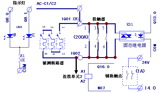
Control system completed functions
The test system has the same structure for each test unit, as shown in the figure below. On the left is the indicator light for each channel. The normal operation is green, the trip is red, and (Q8.0~Q12.7) is not displayed. The right side is the circuit breaker under test, the bypass contactor (Q16.0~Q18.3), and the bypass solid state relay (Q13.0~Q15.3). The auxiliary contact is used to detect whether the current circuit breaker is closed or open (I4.0~I6.3), and the addresses of the lamp, contactor, relay and auxiliary input are sequentially increased.
In the program we consider using loop plus indirect addressing to achieve:
L +20
T MB0 //cycles
L 2#0000_0000_0010_0000 (I4.0) //Auxiliary input start address
T MD2
L 2#0000_0000_0100_0000 (Q8.0) //Output green light start address
T MD6
L 2#0000_0000_0100_0001 (Q8.1) //Output red light start address
T MD10
L 2#0000_0000_0010_0000 (Q13.0) //Output contactor start address
T MD14
L 2#0000_0000_0010_0000 (Q16.0) //Output solid state relay start address
T MD18
NEXT:
L MD2
INC 1
T MD2 //Auxiliary input address plus 1
L MD6
INC 2
T MD6 //Green light output address plus 2
L MD10
INC 2
T MD10 //Red light output address plus 2
L MD14
INC 1
T MD14 / / control contactor output address plus 1
L MD18
INC 1
T MD18 //Control solid state relay output address plus 1
L MB0
LOOP NEXT //20 group finished?
...
Applying this structure makes the program very simple, debugging is very convenient, once a certain function changes, the modification is convenient, if the actual address is used, the corresponding place of each group has to be modified.
summary
The application of CP 340 makes Siemens products communicate with other devices conveniently. The STEP 7 indirect address programming method is very effective. The circuit breaker limit current test system is actually running well after completion in 2005.
S7-300 PLC and DCS serial communication
With the improvement of communication software in PLC and DCS manufacturers and the strengthening of power engineering in equipment bidding, equipment manufacturers strongly recommend the use of serial communication as the signal connection between PLC and DCS. This example takes the communication between the Siemens S7-300 PLC (CP341 communication card) used in the boiler plasma ignition system of the 2×600 MW unit project of the DH power station and the Siemens DCS control system TELEPERM XP (CM104 communication module) as an example. The specific steps of implementing MODIBUS RS-232C/RS-485 communication are described, and the hardware configuration, connection and software configuration of the system are described.
System connection
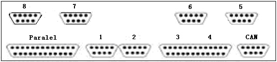
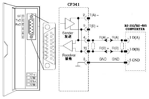
TELEPERM XP configuration module communication processor CM104 as a "master" (MASTER), supports MODBUS protocol, and provides six 9-pin RS-232C serial interface (Serial 3 ~ Serial 8), as shown below. Since the communication distance exceeds 15m, the CP341-RS422/485 card is selected as the "slave" (SLAVE) in the configuration of the S7-300 PLC and DCS. The card provides a 15-pin serial interface. Support MODBUS protocol, the design uses PHOENIX company's PSM-EG-RS-232C/RS-485-P/ZD module as RS-232C to RS-485 interface adapter.
Adapter internal jumper setting: RS-485 BUS-END is ON, and DTE/DCE is selected as DCE, which is the data circuit terminating device side. The standard 9-pin serial cable is used between the CM104 and the adapter. When the CP341 and the adapter are used for RS-485 communication, the 2-core shielded cable is used. The wiring is as shown below.
CP 341 module application brief
CP 341 is S7-300 point-to-point communication module, hardware interface adopts RS-232, TTY, RS-422/RS485 (X27) mode; software protocol includes MODBUS, 3964(R), R512K and ASCII; this project applies MODBUS SLAVE protocol.
MODBUS is an industrial fieldbus communication protocol. The master/slave mode, after the master sends a request, the slave responds to the request data, and the data response content responds according to the function code. The following table shows the data type corresponding to the function code of the CP341 application.
Table CP341 Applicable function code corresponding to the data type
function code | data | type of data | access | address | |
01,05,15 | Coil (output) status | Bit | Output | Read/write | 0XXXX |
02 | Output status | Bit | enter | Read only | 1XXXX |
03,06,16 | Holding register | 16-bit register | Output register | Read/write | 3XXXX |

FC21 FC with SEND
FC22 FC with RECEIVE
DB21, DB22 Instance DBs for the standard FBs
DB40, DB41 Work DBs for the standard FBs
DB42 The source DB for send
DB43 The destination DB for receiveddata
OB1 Cyclic OB
OB100 Restart (warm start) OB
VAT1 Variables table
FB7, FB8 Standard FBs forRECEIVE, SEND
SFC58,59 SFCs for the standardFBs
After programming "Blocks", put the CPU in the "RUN" position, the CP341 can communicate with the serial port.
(2) Programming of communication parameters
Modbus Slave Address: 1
Port: RS485
Baud rate: 19200
Date Bits: 8
Parity: None
2.CM104 software configuration
The control configuration of the CM 104 includes the hardware configuration and various input and output configurations, which are not described here. The configuration of the communication parameters is mainly written into the CM.INI file through its programming interface Serial 1, involving a total of 14 configuration items, some of which are conventional configuration items, which can be the default values ​​of the system. For example, the following configuration items that must be completed are used:
Modbus Master on (Serial 5)
[ModbusMaster_3]
PortAdr=0x380
Irq=5
Baudrate=19200
Parity=NONE
StopBits=1
DataBits=8
RCS-Offset=-1;Modifier for addresses related to function code 1 (read coil status)
RIS-Offset=-1;Modifier for addresses related to function code 2 (read input status)
RHR-Offset=-1;Modifier for addresses related to function code 3 (read holding register)
RIR-Offset=-1; Modifier for addresses related to function code 4 (read input register)
FSC-Offset=-1;Modifier for addresses related to function code 5 (force single coil)
PSR-Offset=-1; Modifier for addresses related to function code 6 (preset single register)
RtsCts=1
Delay=200
Timeout=1000
Dummys=5
Precautions during implementation
When the connection and configuration work correctly, the PLC and DCS will enter the normal data communication state. This can be reflected from the status light of the card.
There are three status indicators on the CP341, namely: SF (RED) indicates error status; TxD (GREEN) indicates data is transmitted; RxD (GREEN) indicates data is received. The TxD and RxD status lights flash alternately when communication is normal.
The status indicators on the CM104 are: POWER (ORANGE) indicates that the CM104 is powered; RESETR (RED) indicates reset; HDD (GREEN) indicates read and write to the internal memory at startup; SCSI (GREEN) indicates the status after the external SCSI device ; LAN (GREEN) indicates the connection state with the TXP bus, flashing green when normal; LAN100 (GREEN) indicates the connection rate; USER1 (GREEN) indicates the state of communication with the TXP, normally no display; USER2 (GREEN) indicates The status of the third-party device communication, no display when normal.
There are two lights on the PHOENIX interface adapter, namely: CTS (ORANGE) indicates that data is being transmitted; RTS (GREEN) indicates that data is being received. When the communication is normal, the CTS and RTS status lights flash alternately.
When the communication is not normal, the status indicator of the card immediately displays the error status. In this case, check the hardware error and check the software error. For example, the diagnostic information of the function block is configured by software to find the cause of the fault. In software programming, pay attention to the following two points:
1 To ensure that the communication rate between the PLC and the DCS is the same, it is recommended to use a rate of 9600 bit/s or 19200 bit/s, and it is better not to increase the parity;
2 To ensure the validity of the communication data address, the address offset can be set in the CM104.
In terms of hardware, pay attention to the following aspects: Make sure to use shielded ITP cable; at the same time, be sure to connect the positive terminal to the positive terminal when wiring.
summary
After the implementation of the communication, there is a significant improvement in the quality and maintenance of the transmitted signal. However, when there are other protocol conversion devices in the system, the real-time performance is slightly insufficient. All monitoring and control on the S7-300 PLC can be carried out on the DCS, and the engineering cost is significantly reduced compared with the hard wiring.
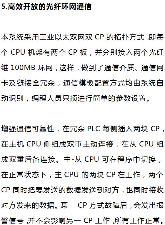
Application of S7-300/400 PLC in permanent ship lock system


1. Ship lock control system
The electric control system of each lock of the ship lock is mainly composed of a centralized control system, 12 local substation control systems, 14 sets of drainage control systems, one bridge crane and four anti-collision warning devices.
The automatic monitoring devices for each line of ship locks consist of one centralized control main station, 12 sets of local control substations and navigation signal devices, broadcasting command equipment, ship detection and industrial TV monitoring and management devices and other peripheral equipment. The centralized control master station consists of two redundant S7-400 PLCs, and the local control substation consists of 12 redundant S7-400 PLCs. The drainage control system, bridge crane and anti-collision warning device are composed of S7-300 PLC.
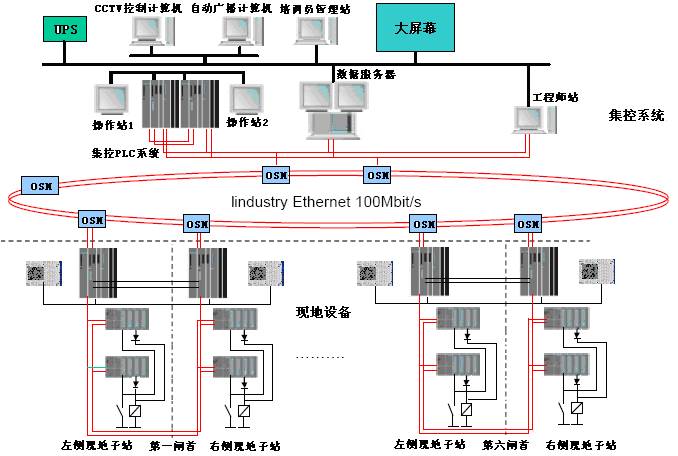
The main functions of the system are responsible for the real-time process data acquisition, centralized control, operation and other functions of the continuous gate operation of each line of ship locks, as well as the communication control between the centralized control system and the local control system. The main work of the substation is to control the hydraulic pump station, the herringbone work gate, the water delivery working valve, the anti-collision device and the navigation signal commanding equipment for operating the gate. In order to ensure the safe operation of the system and timely collection of various information, the centralized control system and the local control system are connected through redundant double-loop optical fiber industrial TCP/IP Ethernet network and optical fiber switching module (OSM) and optical redundancy management module (ORM). The block diagram is shown below.


Gate closing condition: The valve and locking device are in non-operating state, and there is no Class B fault in the first substation of this gate.
Valve opening condition: the adjacent gate valve is closed, the gate locking device is not in operation, and there is no Class B fault in the first substation of the gate.
Valve closing condition: The gate locking device is not in operation, and there is no Class B fault in the first substation of the gate.
Basic configuration of the ship lock control system
Each centralized control station consists of 4 power modules, 2 central processing units (CPU-417H), 4 communication modules (CP443-1), 2 ET200 remote stations, 8 digital input modules (DI), 6 A digital output module (DO), two operator panels PC670 and so on. Each local control substation consists of one power module, one central processing unit (CPU-417H), two communication modules (CP443-1), four ET200 remote stations, two analog input modules (AI), Two analog output modules (AO), 15 digital input modules (DI), 8 digital output modules (DO), 2 SM338 modules, and operator panel TP37.
In order to ensure the stability of the system, the redundant and fault-tolerant features of the S7-417H are utilized, and the centralized control station is redundant. The two PLCs on both sides of the same control gate of the local control substation are synchronized by two optical cables. The distributed processing DP interfaces on the two CPUs are respectively connected to a PROFIBUS field bus to realize redundant communication between the CPU and the field I/O; and the redundant industrial high-speed Ethernet Ethernet network using TCP/IP communication protocol is connected. Communication between PLCs and computer monitoring systems. The PLC configuration diagram of the local substation control system is shown in the figure below.

Each substation is a basic control unit of the overall operation automatic monitoring system of the first-line ship lock. In addition to the basic functions of the local operation control, it should also be able to accept the program control commands of the centralized control station, automatically work on the herringbone gates and water delivery. Local equipment such as corridor working valve, anti-collision warning device and navigation command signal device are operated and controlled; collecting hydraulic station system information, on-site gate valve opening degree, position information, water level detection data and adjacent gates to ensure safe operation Blocking information, outputting an operation execution instruction after preprocessing. The site information is sent back to the centralized control station. Based on the information, the centralized control station makes control decisions and automatically completes the monitoring task of the overall operation of the ship lock, so that the vessel (team) can pass through the ship efficiently and safely.
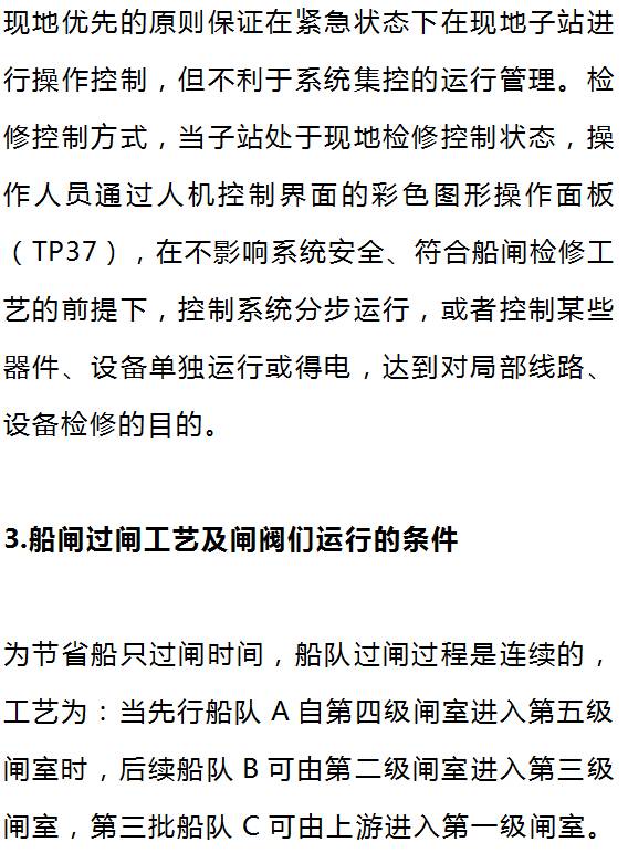
Control characteristics of Siemens PLC in ship lock system
1. Left and right gate PLC realizes hardware hot standby and event synchronization
Two PLC stations on the left and right gates realize unconditional automatic bumpless switching. When one of the two PLC stations that are hot standby is working as the primary station, the herringbone gates on both sides of the gate are simultaneously controlled. Under the synchronization of the optical synchronization modules on the two PLC stations, all data and operating states installed on the opposite bank as slave CPUs are identical to the master CPU, but the slave output is disabled. When the primary station fails to work normally (such as power supply, CPU is bad, DP port is bad, and the synchronization module is bad), the slave station will automatically switch to the primary station unconditionally due to the event synchronization mechanism, and the switching time is ≤10ms.
All modules on the PLC station can be plugged in and out. After the original station is repaired, it will work as a slave. The current master station CPU program and process data will be automatically filled to the repaired slave CPU, so that the slave CPU data and working status are The main station is consistent.
2. PLC programming and maintenance is very simple
Since the CPU of the S7-417H is designed for redundant systems, its CPU hardware system and operating system built into the CPU ensure that the system user is programmed to face a non-redundant stand-alone system. The management of the redundant system is completely left to the system to complete automatically. In other words, after the user-selectable software package performs simple parameter setting on the redundant system, after downloading the program to any CPU that is hot standby, the program will automatically copy to Another CPU. Therefore, the user program can be easily converted from a stand-alone program to a redundant CPU program, and vice versa.
The S7-417H fully supports online programming, configuration and debugging. All modules (including network communication) can be plugged in and out without any initialization work, which makes field maintenance very convenient. The CPU417H operating system upgrade can also be performed online.
3. Adopt advanced network technology
The I/O is connected via a PROFIBUS redundant network to make the system structure simple and reliable. The two PROFIBUS-DP network cables are connected to the two DP interfaces of the IM153-3 at the same time. The input signals obtained from the two sensors at each measuring point are respectively sent to the input module of the ET-200 station, and through the IM153-3 and the redundant PROFIBUS. - The DP network cable is simultaneously transmitted to each CPU.
When two PROFIBUS-DP networks work normally, but one of the IM153-3's DP ports fails, the system does not switch between the CPU or PROFIBUS-DP network. The IM153-3 uses another DP port to send data to the corresponding CPU through a DP network, and transmits data from the CPU to the main CPU through the fiber hot standby line. At the same time, the output of the DP port is activated only. When different network segments and DP ports on the two DPs fail, you can use another network segment or DP port to communicate with the CPU, which greatly improves network reliability, instead of a simple dual network, thus minimizing the CPU. The switching greatly reduces the CPU synchronization time caused by CPU switching and improves the CPU operating efficiency.
When an IM153-3 module is completely damaged, because the system is equipped with two sensors for the same measuring point, the other IM153-3 template acquires signals from the connected sensors and is connected to the dual redundant PROFIBUS-DP network. Signals are sent to both CPUs. The IM153-3 template can be replaced online, and the two DP interfaces of the IM153-3 can also be replaced online, making it easy to repair the system.
4. PLC input and output unit communication
The distributed processing DP interfaces on the two CPUs are each connected to a PROFIBUS fieldbus to implement redundant communication between the CPU and the field I/O. The two PROFIBUS-DP network cables are simultaneously connected to the redundantly configured IM153-2 module on the ET-200M station, so that the input and output signals communicate with two mutually hot standby CPUs via the redundant IM153-2 and PROFIBUS-DP network cables. When the IM153-2 module communicating with the main CPU fails, the system does not implement switching between the CPU or PROFIBUS-DP network, but automatically sends data to the corresponding CPU through another DP network and passes the optical fiber. The hot spare line transfers data from the slave CPU to the master CPU. Therefore, the CPU switching is minimized (the CPU synchronization time difference occurs when the CPU switches), and the operating efficiency of the CPU is improved. The IM153-2 template can be changed online, and the PROFIBUS network can be replaced online, making it easy to repair the system. The current substation communication network diagram is shown below.

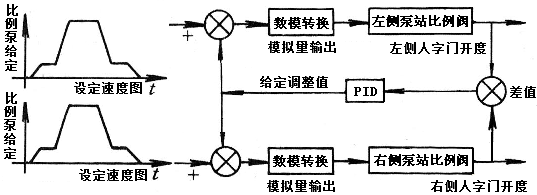
When the program is running, the difference of the opening degree of the herringbone door is detected. According to the difference of the opening degree, the proportional pump voltage adjustment value is given after the PID calculation to change the running speed of the miter gate. At the same time, the range and amplitude of the adjustment value are limited to prevent the flip-flop from running too fast and shaking. Class A alarm when the difference in the opening of the herringbone gate exceeds the set range of 20 mm.


A manual pulse generator (MPG) is a device normally associated with computer numerically controlled machinery or other devices involved in positioning. It usually consists of a rotating knob that generates electrical pulses that are sent to an equipment controller. The controller will then move the piece of equipment a predetermined distance for each pulse.
The CNC handheld controller MPG Pendant with x1, x10, x100 selectable. It is equipped with our popular machined MPG unit, 4,5,6 axis and scale selector, emergency stop and reset button.
Manual Pulse Generator,Handwheel MPG CNC,Electric Pulse Generator,Signal Pulse Generator
Jilin Lander Intelligent Technology Co., Ltd , https://www.jilinlandermotor.com