Instrumentation Amplifier Advantages - Instrumentation Amplifiers Typical Applications and Examples
With the rapid development of electronic technology, operational amplifier circuits have also been widely used. The instrumentation amplifier is a precision differential voltage amplifier that is derived from an operational amplifier and is superior to an operational amplifier. The instrumentation amplifier integrates key components into the amplifier. Its unique structure makes it highly common mode rejection ratio, high input impedance, low noise, low linearity error, low offset drift gain setting flexibility, and ease of use, making it in the data Acquisition, sensor signal amplification, high-speed signal conditioning, medical instruments, and high-end audio equipment are all highly favored.
This article first introduced the principle and characteristics of instrumentation amplifiers, followed by the advantages of instrumentation amplifiers, and finally introduced typical applications and examples of instrumentation amplifiers.
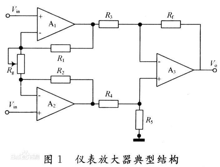
Instrumentation Amplifier PrincipleThe typical structure of the instrumentation amplifier circuit is shown in Figure 1. It is mainly composed of a two-stage differential amplifier circuit. Among them, the op amps A1, A2 are in-phase differential input mode, and the non-inverting input can greatly increase the input impedance of the circuit and reduce the attenuation of the weak input signal; the differential input can make the circuit only amplify the differential mode signal, and The input signal of the module only acts as a follower, so that the common mode rejection ratio is improved. In this way, in the differential amplifier circuit composed of the operational amplifier A3 as the core component, the precision matching requirements of the resistors R3 and R4, Rf and R5 can be significantly reduced under the same requirement of the common mode rejection ratio, so that the instrumentation amplifier circuit can be Simple differential amplifier circuits have better common-mode rejection. Under the condition of R1=R2, R3=R4, and Rf=R5, the gain of the circuit of FIG. 1 is: Au=(1+2R1/Rg)(Rf/R3). It can be seen from the formula that the adjustment of the circuit gain can be achieved by changing the Rg resistance. The typical structure of the instrumentation amplifier is shown in Figure 1.
The instrumentation amplifier is a high-gain, dc-coupled amplifier with differential input, single-ended output, high input impedance and high common-mode rejection ratio, low noise, low linearity error, low offset voltage and offset voltage drift, low input bias Current and offset current error characteristics.
Instrumentation Amplifier Benefits1, high common mode rejection ratio
The instrumentation amplifier has the ability to eliminate any common-mode signal (the same potential at both inputs) and amplify differential-mode signals (potentials at the two input terminals are different). In order for the instrumentation amplifier to operate properly, it requires that it both amplify the microvolt-level differential-mode signal and at the same time suppress several volts of common-mode signals. Instrumentation amplifiers that implement this function must have high common-mode rejection. The typical value of common-mode rejection ratio is 70- 100dB. Generally, the performance of CMRR is improved at high gain, that is, CMRR is high at high gain and low at low gain.
2, smaller linear error
Both the input offset and the scaling factor can be corrected by external adjustments. The linearity error is an inherent defect of the device and cannot be eliminated by external adjustment. Therefore, the small linear error of the instrumentation amplifier is achieved by the manufacturer through the use of advanced production technology and chip structure design. For a high-performance instrumentation amplifier, the linearity error is 0.01%, and some even reach 0.0001%.
3, high input impedance
The impedance of the signal source may be very high or unbalanced in the actual application circuit. In order to be well matched, the input impedance of the instrumentation amplifier is not only high, but also has good matching performance. The input impedance is typically 109 - 1012 ohms.
4, low noise
Instrumentation amplifiers are often used in harsh environments to complete the picking and preprocessing of weaker signals, so it is required to be a low-noise device and the signal to noise ratio is too low to work. Under normal conditions, the noise referred to the instrumentation amplifier input should be less than 10nV/Hz when the input signal frequency is 1kHz. In order to improve the signal-to-noise ratio, it is generally not desirable for the instrumentation amplifier to add its own noise to the signal.
5, low offset voltage and low offset voltage drift
Instrumentation amplifier offset voltage drift consists of two parts, and input and output parts. Each part has an effect on the total gain, but the offset drift of the input part will become the main source of error when the gain is increased, and the effect of the output part can be ignored. Typical input and output offsets are 100 V and 2 mV. In addition, the instrumentation amplifier has excellent stability. When the operating conditions change, its key parameters remain stable. And easy to use, only need to detect the potential difference between the two inputs. In addition, due to its high degree of integration, the main components are all inside the chip and there are few external components.
Instrumentation Amplifiers Typical Applications1, high-side monitor
The simplest high-side monitors usually require a precision op amp and some precision resistors. Common high-side measurements use classical differential amplifiers (used as gain amplification and high-edge-to-ground level conversion, see Figure 6). Although split circuits are used in many applications, their input impedance is low and there is a large difference in resistance. The matching of resistors must be very accurate to achieve an acceptable common-mode rejection ratio. Any deviation of 0.01% in any resistor value will reduce the CMRR to 86dB; if the deviation is 0.1%, it will reduce the CMRR to 66dB; A 1% deviation will reduce the CMRR to 46dB. When selecting an instrumentation amplifier structure, there is a parameter that requires special attention, that is, at any output swing of the amplifier, the input common-mode voltage range should include a high-side voltage plus a safety margin.
2, level converter
The working principle of this circuit can be understood in this way. Think of the MAX4198 as a three-input sum amplifier (as shown in Figure 7) whose voltage transfer function is Vout=Vb-Va+Vshift. This equation shows that the output is derived from the differential signal and the REF input. The algebraic sum of the voltages determines that VREF can be any value. It does not saturate the MAX4198's amplifier output. The MAX4194 is also suitable as a precision amplifier. It can be easily configured to have the following fixed gains: -1, 2, or ±1.
3, stress measurement
The real advantage of the three op amp topology is its ability to make true differential measurements (very high CMR) and at the same time very high input impedance, which makes it widely used, especially in applications where the signal source impedance is very high. . In order to minimize the leakage current from the signal source to the ground, some protection techniques are used in this example. The signal source cable is a shielded cable and its shield isolation layer is connected to (Vcm+ΔV/2). Figure 8 shows an amplifying circuit including a Wheatstone bridge sensor. The bridge impedance of the circuit can be appropriately reduced without reducing the CMR value of the instrumentation amplifier.
Instrumentation Amplifier Application Examples_TI Instrumentation Amplifier ApplicationsINA128:
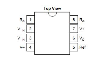
Figure 1 pin layout
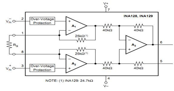
Figure 2 internal schematic
The 1 and 8-pin access resistors are used to set the amplification factor. The amplification calculation formula is G=1+50KΩ/RG. 5 Pins can be grounded directly. Its supply voltage range is ±2.25~±18V, with low offset voltage, low bias current, and high common mode rejection ratio.
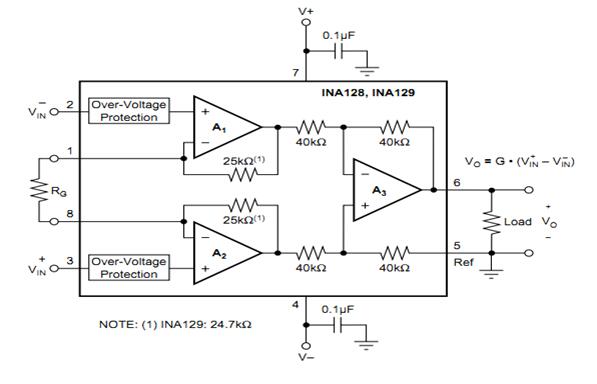
Figure 3 Typical connection of application circuit
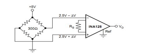
Figure 4 bridge method circuit connection
The left face is divided into measuring bridges, and the perceived signal changes into a voltage signal. This small signal can be amplified for subsequent processing. If the signal is weak, the bridge is best used in the application. This method has the highest sensitivity. Improve signal accuracy.
In addition, INA118 and INA217 are all instrumentation amplifiers, and their pin functions and structure are the same as INA128.
LED Wall Wash Light
Wall Wash Light Series Include 36x12w LED Wash light, 19x15w Led wash light; Both is hot selling in the lighting market.
36X12W RGBW 4 IN 1/5 IN 1/6 IN 1 /LED Wash Moving Head Light
Specification:
Pure bright in color effect, excellent color mixing, good heat cooling
36 pcs 12W RGBWA+UV 6in1 LED, 36 pcs 10W RGBWA 5in1 LED, 36 pcs 10W RGBW 4in1 LED
10-60 zoom angle, narrow beam effect to wide wash effect, functional in usage.
Small size, easy to carry and install, each unit weighs only 9kg
Linear smooth dimmer from 0-100%, 1-20 times strobe per second, flicker-free for TV and films.
Suitable for mobile productions, events, parties, stage installations, theater, musical concert, TV studios.
Our company have 13 years experience of LED Display and Stage Lights , our company mainly produce Indoor Rental LED Display, Outdoor Rental LED Display, Transparent LED Display,Indoor Fixed Indoor LED Display, Outdoor Fixed LED Display, Poster LED Display , Dance LED Display ... In additional, we also produce stage lights, such as beam lights Series, moving head lights Series, LED Par Light Series and son on...
Wall Wash Light Series,Disco Light,Led Washer Light,Moving Head
Guangzhou Chengwen Photoelectric Technology co.,ltd , https://www.cwledpanel.com