Introduction to the calculation method of sky wave propagation attenuation
The calculation model of short-wave sky wave propagation attenuation prediction is established to provide reference for ensuring the reliability of short-wave communication circuits. The established method is mainly based on ITU-R P.533-7. Firstly, the propagation path is discriminated, and then the frequency prediction is carried out. Finally, the propagation attenuation calculation model is established and compared with the literature results. The two have good consistency. The frequency prediction part abandons the global prediction method in ITU-R P.533-7 and adopts the sub-method that is more accurate for China.
Sky waves are waves that propagate through the reflection of the ionosphere, also known as ionospheric waves. The ionosphere is composed of solar radiation, and the intensity of the sun's exposure varies from year to year and from moment to moment. Therefore, the conditions of the ionosphere vary from place to place. The ionization conditions of the ionosphere are constantly changing, making the short-wave channel propagating through the sky wave unstable, which is essentially a time-varying dispersion channel. Path attenuation, delay spread, atmospheric noise, and interference of short-wave channels are constantly changing with time, place, season, day and night, and frequency. Therefore, in short-wave communication, in order to ensure communication reliability, it is necessary to predict the sky-wave frequency and propagation attenuation for each specific communication circuit. This paper establishes the calculation model of short-wave sky-wave propagation attenuation based on the recommendations of ITU-R P.533-7, and compares the calculation results with the reference literature and implements software simulation.
Discrimination of 1 day wave propagation pathThe short-wave sky wave mainly travels long distances by the reflection of the ionosphere. The ionosphere is layered, and its range extends from about 50 km above the surface of the earth to about 2 000 km. According to the distribution of electron concentration, the ionosphere usually divides. The three layers are called D layer, E layer and F layer from bottom to top. During the day, the F layer can also be subdivided into the F1 and F2 layers, and the F2 layer is located on the ground.
Above 220 km, it plays a major role in short-wave communication. The short-wave sky wave propagation path is mainly determined by the reflection of the E layer and the F2 layer.
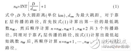
After the position of the transmitting and receiving point of the short wave communication is determined, the minimum number of hops that are reflected by the E layer and the F2 layer is determined by the equation (1).
To establish reliable short-wave communication, one frequency cannot be arbitrarily selected in the short-wave band. On a given distance and direction path, short-wave communication can only use a limited frequency band for a certain period of time. For long-term short-wave communication circuits, several frequencies are usually required for selection at different times. After considering the most important propagation conditions affecting sky-wave propagation, the operating frequency of short-wave communications can be predicted. Since the condition of sky wave propagation varies with the number of sunspots, the sunspot number can be used as an important variation factor of short wave propagation to determine the "limit frequency curve" propagated through the E and F2 layers under the maximum and minimum values ​​of sunspots. ". The limit frequency curve shows the 24-hour variation of the frequency reflected by the E and F2 layers, which can be used to determine the highest available operating band (ie, MUF) under normal propagation conditions. The choice of working frequency should generally be no higher than MUF. When relying on F2 layer reflection, the optimal working frequency is chosen to be 0.85MUF. When relying on E layer reflection, the optimal working frequency is chosen to be MUF, which is because E layer is relatively stable.
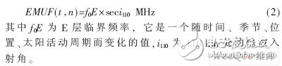
2.1 E layer maximum available frequency prediction
The maximum available frequency of the E layer is predicted according to the calculation method provided in Reference [1]. The calculation formula is as follows:
2.2 F2 layer maximum available frequency prediction
Predicting the maximum available frequency of the F2 layer requires prediction of two important parameters, namely the critical frequency f0F2 of the F2 layer and the prediction of the transfer factor M(3 000)F2 of the F2 layer 3 000 km. The calculation model of these two parameters (for China) The empirical coefficients of the sub-large method model are generally obtained from the data of the ionospheric detection. The maximum available frequency of the F2 layer is determined by:
2.3 E layer maximum cutoff frequency prediction
In order to judge whether it depends on the E layer or the F2 layer propagation, the calculation of the maximum cutoff frequency of the E layer is required. When the operating frequency is less than the maximum cutoff frequency of the E layer, it is considered that the frequency is blocked by the E layer and there is no F2 layer propagation mode, the E layer. The formula for calculating the maximum cutoff frequency is:
3.1 Field strength calculation of any propagation path receiving point
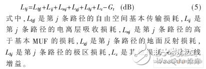
If the short-wave system is considered to be a closed transmission system, starting from the transmitter output and ending at the receiver input, the total line loss is free space loss, ionospheric loss, ground reflection loss, higher than MUF loss, pole loss and other losses. .
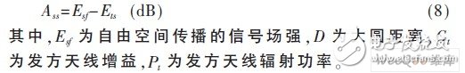
(1) The calculation expression of any short-wave sky wave propagation path loss is:
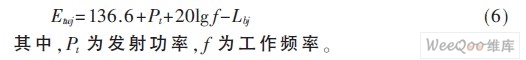
(2) The receiving field strength of any short-wave sky-wave propagation path is:
3.2 Multi-path synthetic field strength calculation at the receiving point
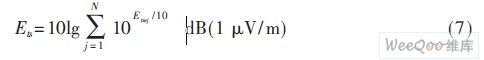
The power field superposition of each receiving point is superimposed, and the equivalent synthetic field strength can be calculated. The calculation formula is:
3.3 Propagation attenuation calculation
The calculation method of sky wave propagation attenuation is to subtract the combined field strength of the receiving point by the signal field strength propagated in free space, namely:
In order to verify the accuracy of the model calculation, the sky wave propagation attenuation calculation software of this paper is compared with the results provided in the reference [4]. Since there is no data of the combined field strength and total attenuation of each path in Reference [4], the main data in the calculation process are mainly compared, and the consistency of the calculation results of each parameter in the calculation process, such as frequency and path loss. The agreement of the calculation results can completely guarantee the consistency of the final attenuation calculation results.
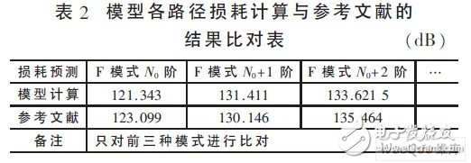
A specific circuit listed in reference [4]: ​​transmitting point latitude and longitude (112.78, 35.08), receiving point latitude and longitude (113.99, 33.08), time is May 11, 2004, receiving antenna gain 3.373 7 dB, transmitting power 10 kW, the operating frequency is chosen to be 7 MHz and the number of sunspots is 40. The results of model calculation and literature comparison are shown in Table 1.

Since the operating frequency of 7 MHz is greater than the shielding frequency of the E layer, the electric wave penetrates the E layer and relies on the F2 ionosphere for reflection. Therefore, only the loss of each mode of the F2 layer is calculated. The results of the model calculation and the literature comparison are shown in Table 2. Shown.
In this paper, the reference model [2] is used to establish a calculation model for the short-wave sky-wave propagation attenuation within 7 000 km. The model simulation results are consistent with the calculation results of the reference [2]. The sky wave calculation process shows that the accuracy of frequency prediction has a great relationship with the empirical coefficient of ionospheric detection induction. In addition, the attenuation calculated in this paper is relative to the free space, such as the calculation of the basic transmission loss, plus the loss of free space.
references
[1] Rec.ITU-R P.1239 ITU-R REFERENCE IONOSPHERIC CHARACTERISTICS.
[2] Rec.ITU-R P.533-7 HF propagaTIon predicTIon method.
[3] Sun Xianru. F2 ionospheric prediction method in the sub-region [J]. Journal of Communications, 1987, 11(6): 37-45.
[4] Beijing Design Institute, Ministry of Posts and Telecommunications. Telecom Engineering Design Manual - Shortwave Communication [M]. Beijing: People's Posts and Telecommunications Press, 1991.
Outdoor Fibre Termination Box,Fiber Optic Distribution Cabinet,Wall Mount Fiber Distribution Box,Distribution Box Fiber Optic
Ningbo Fengwei Communication Technology Co., Ltd , https://www.fengweicommunication.com