New lithium ion battery linear charging solution
Lithium-ion batteries have gradually replaced traditional nickel-cadmium, nickel-hydrogen batteries and lead-acid batteries with their high energy density, excellent charge and discharge performance, and no pollution. They are widely used in modern portable electronic products.
Compared with other types of batteries, lithium-ion batteries have higher performance requirements for chargers. These requirements are mainly reflected in the control of the charging process and lithium battery protection, which is characterized by a large charging current and high. Accurate charging voltage, staged charging mode and perfect protection circuit.
Chip introduction
The SE9018 is a constant current/constant voltage mode lithium-ion battery linear charging chip with an internal PMOSFET architecture and integrated anti-reverse charging circuit, eliminating the need for an external isolation diode.
The chip preset charging voltage is 4.2V, the accuracy is ±1.5%, the charging current can be set by an external resistor, and the maximum continuous charging current can reach 1A. When the chip is due to large working power, high ambient temperature or poor PCB heat dissipation performance, etc. When the junction temperature is higher than 140 °C, the internal thermal feedback circuit will automatically reduce the charging current and control the chip temperature within the safe range. In order to enable the chip to maintain efficient operation, measures should be taken to minimize the chip operating power and chip temperature. For example, the input terminal is connected in series with a small resistor (reducing the input voltage), increasing the PCB heat dissipation copper foil area, and making the chip heat sink and PCB copper foil sufficient. Contact and so on.

Figure 1 SE9018 pin map

Figure 2 Schematic diagram of SE9018
The SE9018 integrates a battery temperature monitoring circuit. When the battery temperature is outside the normal range (too high or too low), the chip automatically stops the charging process to prevent the battery from being damaged due to excessive or too low temperature.
Battery temperature monitoring is achieved by determining the TEMP terminal voltage (VTEMP), which is provided by a resistor divider network that includes the internal NTC thermistor.
When VTEMP is between 45% & TImes; VCC and 80% & TImes; VCC, the chip determines that the battery temperature is within the normal range; when VTEMP "45% & TImes; VCC or VTEMP" 80% & TImes; VCC, the chip determines the battery temperature High or low; battery temperature monitoring is disabled when the TEMP terminal is grounded.
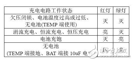
The SE9018 contains two open-drain status indication outputs CHRG and STDBY. When the circuit is in the charging state, the CHRG terminal is low and the STDBY terminal is high-impedance. When the battery is full, the CHRG terminal becomes high-impedance. The STDBY terminal is set low. When the battery temperature monitoring function is normally used, if the chip is not connected to the battery or the battery temperature is out of the normal range, the CHRG terminal and the STDBY terminal are both in a high impedance state; when the battery temperature monitoring function is disabled, if the chip is not connected to the battery, the STDBY terminal is Low level, CHRG terminal output pulse signal.
Other features of the SE9018 include manual shutdown, undervoltage lockout, automatic recharge, and more.
A typical SE9018-based lithium-ion battery charging circuit is shown in Figure 3. When the CE terminal is high, the SE9018 works normally.

Figure 3 SE9018 typical application circuit
1. Setting of charging current
The charging current Ibat during constant current charging is set by the resistance Rprog between the PORG terminal and the GND terminal. The relationship between Ibat and Rprog resistance is:

Formula 1
For example, if a constant charging current of 1 A is desired, Rprog = 1,200 Ω can be obtained according to Equation 1.
2. Battery temperature monitoring circuit setting
The setting of the battery temperature monitoring circuit is mainly to set R1 and R2. It is assumed that the resistance of the NTC thermistor at the lowest operating temperature is RTL, and the resistance at the highest working temperature is RTH (the data of RTL and RTH can be checked) Or by experiment), the resistance values ​​of R1 and R2 are:
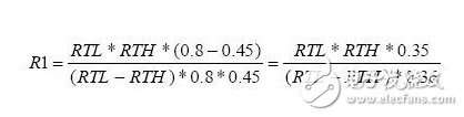
Formula 2
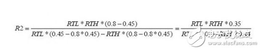
Formula 3
In practical applications, R2 can be removed if only high temperature protection is required and low temperature protection is not required. At this time, the resistance of R1 is:
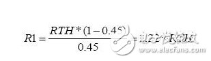
Formula 4
3. Manual shutdown settings
During the charging process, the SE9018 can be placed in the shutdown state at any time by setting the CE terminal low or removing Rprog (PROG terminal floating). At this time, the battery leakage current drops below 2uA, and the input current drops below 70uA.
4. Undervoltage lockout state
If the input voltage VCC is lower than the undervoltage lockout threshold or the difference between VCC and the battery voltage Vbat is less than 120mV, the SE9018 is in an undervoltage lockout state.
When the chip is in the shutdown state or undervoltage lockout state, both the CHRG terminal and the STDBY terminal are in a high impedance state.
5. Normal charging cycle
When the input terminals of the SE9018 and the battery are in a normal state, the charging circuit enters a normal charging cycle, and the cycle includes four basic working modes: trickle charging, constant current charging, constant voltage charging, charging end and recharging.
If the battery voltage Vbat is lower than 2.9V, the charging circuit enters the trickle charging mode, and the charging current is one tenth of the constant current charging current (if the constant current charging current is set to 1A, the trickle charging current is 100mA) The trickle charge state will be maintained until the battery voltage Vbat reaches 2.9V. The trickle charge mode is mainly to avoid damage caused by high current surge to the internal structure of the battery when the battery voltage is too low.
When the battery voltage is higher than 2.9V but less than the preset full-charge voltage of 4.2V, the charging circuit is in the constant current charging mode. As described above, the charging current is determined by Rprog.
When the battery voltage reaches 4.2V, the charging circuit enters the constant voltage charging mode. At this time, the BAT terminal voltage is maintained at 4.2V, and the charging current is gradually reduced. The main function of this process is to reduce the internal resistance of the battery to the effect of the full voltage, so that the battery is fully charged.
When the charging current is reduced to 1/10 of the constant current charging current, the charging circuit stops charging the battery and enters a low power standby state. In standby mode, the SE9018 continuously monitors the battery voltage. If the battery voltage drops below 4.05V, the charging circuit will recharge the battery.
6. Indicator status
Table 1
7. Circuit compatible with USB power supply and adapter power supply
At the same time, the SE9018 chip can be used to implement the charging circuit for USB power supply and adapter power supply. The circuit diagram is shown in Figure 4.
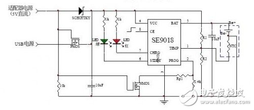
Figure 4 USB and adapter solution
When powered by USB power, the PMOS and NMOS gates are pulled down to low potential, the PMOS is turned on, the USB power supply supplies power to the SE9018, and the SCHOTTKY diode prevents the USB terminal from leaking to the adapter. The NMOS is turned off, Rp1 is turned off, Rprog = 2.4kΩ, and the constant current charging current is 500mA.
When using the 5V adapter for power supply, the PMOS and NMOS gates are high, the PMOS is turned off, preventing the adapter from leaking to the USB terminal, and the adapter 5V voltage is supplied to the SE9018 through the SCHOTTKY diode. When the NMOS is turned on, Rp1 is connected to the circuit. At this time, Rprog is connected in parallel with the 2.4kΩ resistor. By setting Rp1, a constant current charging current greater than 500mA can be realized.
in conclusion
This paper discusses the intelligent high-current lithium-ion battery linear charging solution. The SE9018 chip has the characteristics of fast charging speed, strong battery protection and fewer peripheral components. The chip is also suitable for USB power supply and adapter power supply. It is a more practical intelligent high-current lithium-ion battery charging chip.
Flex Power Supply,Flex Power Supply 80Plus,700W Adapter Server Power Supply,Flex 700W Power Supply
Boluo Xurong Electronics Co., Ltd. , https://www.greenleaf-pc.com