Oscilloscope eye diagram test
Eye diagram testing is an important project for high-speed serial signal physical layer testing. The eye diagram is a graph superimposed by waveforms of multiple bits. It can be seen from the eye diagram: digital signal 1 level, 0 level, signal overshoot, ringing? Is the jitter large? The signal to noise ratio of the eye diagram? Is the rise and fall time symmetrical (duty cycle)? The eye diagram reflects the signal quality at large data volumes and provides the most intuitive description of the quality and performance of high-speed digital signals. Figure 1 shows the eye diagram of a 1.25G signal. It can be seen that the jitter of this signal is large. In addition, in many standards for high-speed digital signals, eye diagram templates for different measurement points are defined. The dark blue portion of Figure 1 is the eye pattern template, and the measured eye pattern cannot touch the template. 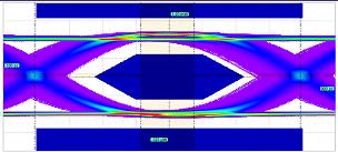 What is BER? In digital circuit systems, the sender sends out multiple bits of data. Due to various factors, the receiver may receive some erroneous bits (ie, bit errors). The ratio of the number of erroneous bits to the total number of bits is called the bit error rate, ie BitErrorRaTIo, or BER for short. The bit error rate is the most important parameter to describe the performance of a digital circuit system. In GHz bit rate communication circuits (such as FibreChannel, PCIe, SONET, SATA), the BER is usually required to be less than or equal to. BER=
It means that 10 bits are transmitted/received, and only 1 bit is allowed to go wrong. When the bit error rate is large, the communication system is inefficient and unstable in performance. Factors that affect the bit error rate include jitter, noise, and the rate of the signal. Bit error rate based eye contour test (BEREyeContour) - LeCroy called ISOBER In the above, the eye diagram is the measurement result of the signal superposition of multiple bits, so it is necessary to pay attention to how many bits of the eye diagram are in the test. consist of? 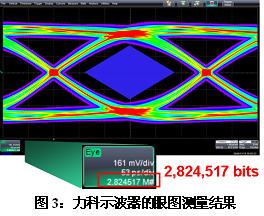
Previous:24V to 5V circuit diagram
Next: Test board
Related Reading
- • [Solution] Application of safety control SCADA system in urban heating monitoring 2016-08-10 14:18
- • [Solution] The tempering furnace acquisition and transmission system based on Dingshengli R-8188 and R-8018 modules 2016-08-10 14:18
- • [Solution] Yokogawa's latest paperless recorder DX2000 in the remote monitoring system of boiler equipment 2016-08-10 14:18
- • [Solution] Multi-parameter telemetry monitoring system based on ZigBee 2016-08-10 14:18
- • [Solution] Introduction of Schneider's complete solution on continuous vertical packaging machine—Schneider Electric (China) Investment Co., Ltd. 2016-08-10 14:18
- • [Solution] Multi-motor power-down synchronous braking of roving frame based on Delta inverter 2016-08-10 14:18
- • [Solution] Schneider's complete solution in the textile printing and dyeing industry - the main chain sub-drive hot air tenter shaping machine control program 2016-08-10 14:18
- • [Solution] Solution of GE Intelligent Platform Products in Power Plant Production Data Monitoring System 2016-08-10 14:18
Pcb Speaker,Pcb Subwoofer,Pcb Mount Speaker,Pcb Mounted Speaker
NINGBO SANCO ELECTRONICS CO., LTD. , https://www.sancobuzzer.com