Overview of HCI and UART structure and principle and design and implementation method of HCI-UART
As a short-range wireless communication technology, Bluetooth technology has great potential for development. This paper intends to develop the application of Bluetooth technology from the HCI layer. This paper first introduces the structure and principle of HCI and UART. Based on the analysis and comparison of the advantages and disadvantages of HCI three types of interfaces USB, RS-232 and UART, this paper proposes an implementation method based on FPGA hardware design HCI-UART. This design is designed in the Quartus II 9.0 integrated design environment using the hardware description language Verilog sub-module. The design is simulated and verified by Modelsim 6.4a.
1 IntroductionBluetooth is a world-class computer and communications company (Ericsson, IBM, tel/'target='_blank'>INTEL, Nokia and Toshiba, etc.) advocated the introduction of an open industry standard for wireless communication technology. It is taken from the alias of the Danish King Harald Bluetooth in the 10th century, intended to form a globally unified standard for wireless communication technology [1]. Bluetooth technology eliminates the connection between devices and replaces traditional wires with wireless connections. Bluetooth mainly consists of Bluetooth hardware and Bluetooth protocol. The Bluetooth hardware consists of analog part and digital part. The analog part refers to the Bluetooth radio transmitter station, and the digital part refers to the main controller. The Bluetooth protocol adopts two kinds of circuit and packet exchange methods, mainly including radio frequency (RF), baseband (BB), link manager (LM), main control interface (HCI, Host CONTROL Interface), embedded driver, HCI. High-level software driver, logical link control adaptation protocol (L2CAP), serial port emulation protocol (RFCOMM), service discovery protocol (SDP), and telephony control protocol (TCS) [2].
At present, there are two ways to develop Bluetooth technology applications: 1) Single microcontroller mode, all Bluetooth transmission protocols and user applications are integrated into one module and completed by one processor. It does not necessarily need the HCI layer, but it involves the hardware protocol layer such as radio frequency and baseband. The development method is complicated, the development cycle is lengthened, and the cost is high. 2) The dual microcontroller mode, the underlying transmission protocol is generally implemented by the Bluetooth hardware module. The embedded microprocessor inside the module becomes the host controller. The high-level transfer protocol and user application are implemented by the host and the main controller respectively. The host and the host controller are connected through a standard physical bus interface [3]. Since the host and the main control layer are completely separated in hardware, the Bluetooth module and the Bluetooth host need to be connected through the HCI layer. In practical applications, due to the complexity and diversity of high-level protocols, users can control the communication process without considering the underlying layer, meet the actual needs of users, and have a short development cycle and good portability. The design is also in this way.
2 system basic principles2.1 UART basic principles
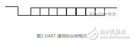
UART (Universal Asynchronous Receive Transmitter), also known as the universal asynchronous receiving and transmitting interface [4], is an asynchronous communication transmission method. The communication protocol frame format consists of five parts: idle state (idle, high level), start bit (start, low level), 5 to 8 data bits, parity (parity, optional), and stop. Bit (Stop, the number of bits can be 1, 1.5 and 2 bits). This format is to synchronize the characters by the start bit and the stop bit, wherein the presence or absence of the parity bit and the length of the data bit are agreed by the communicating parties. After the completion of one frame of data transmission, the next frame of data can continue to be transmitted, or it can continue to be kept at a high level, and the high level between the two frames can be arbitrarily long. The communication protocol frame format specified in this design is: 1 start bit (start, low level), 8 data bits (d0 to d7), 1 bit parity (parity), and 1 stop bit (stop, High level), as shown in Figure 1.
2.2 HCI basic principles
2.2.1 Comparison of HCI transport layers
The HCI layer is located between the Bluetooth high-level protocol and the lower layer protocol. The purpose is to implement interoperability between the host device and the Bluetooth module, that is, the HCI is a software and hardware interface between the Bluetooth host and the host controller. HCI provides a command interface for the baseband controller and link manager in Bluetooth hardware to enable access to the hardware status registrar and control registers, providing a unified access mode to the Bluetooth baseband. Currently, there are three main types of HCI transport layers: USB, RS-232, and UART. In addition, there is a PC Card transport layer, which is not defined in the Bluetooth standard, but is described in the Bluetooth PC Card Transport Layer Version 1.0 white paper published by the Bluetooth SIG in August 1999. Bluetooth does not specify the specifics of the implementation of the PC Card transport layer. Instead, it requires the manufacturer to provide a transport driver to match the HCI driver on the host [5]. Different transport layers have no effect on HCI event processing.
(1) The USB transport layer uses a USB hardware interface on the Bluetooth hardware (the hardware interface has two embedding methods: one is as a USB add/ decrypt chip and the other is integrated on the PC board) [6]. This type of encoding requires that the appropriate driver stack be loaded regardless of which manufacturer's device is used. It also guarantees that the HCI and USB commands are different through the control terminal. The disadvantage is that the software protocol is complex and the software overhead is huge.
(2) RS-232 transport layer: implemented by a physical RS-232 interface between the host and the main controller. Event packets and packets pass through this layer, but the layer does not decode them. The transport layer supports communication between the host controller and hosts in different entities, the communication distance is far, the transport layer specifies the electrical characteristics, and a finer link protocol is adopted to cope with higher line errors. Rate, but need to increase the level shifting circuit on the hardware.
(3) The UART transport layer is similar to the RS-232 transport layer. It also uses a UART serial communication method to transfer data between the host controller and the host. The application environment is mainly for the main controller and the host are on the same circuit board, and the transport layer assumes that the UART communication is wireless. Compared with other systems, the UART transport layer mode is more flexible, and its application environment determines that its connection error is relatively small. A simple reset recovery mechanism can be used to implement the step-by-step reversal. Since the host and the main controller are all on the same circuit board, the transmission layer does not need to specify an electrical signal, and the IC terminal voltages such as TTL and LV-CMOS can be directly used, and the application is more. At the same time, the UART transport layer avoids the cumbersome negotiation and synchronization mechanisms required by the RS-232 transport layer. The UART performance and data throughput level are comparable to those of the USB interface, while the transmission protocol is simpler and reduces software overhead. It is a more cost-effective full hardware solution.
Plastic Package Diode.Among the electronic components, a device having two electrodes allows only the current to flow in a single direction, and many uses apply its rectification function. The Varicap Diode is used as an electronic adjustable capacitor. Most of the diodes have a current directionality that we often call the "Rectifying" function. The most common function of a diode is to allow only current to pass in a single direction (referred to as forward bias) and block in the reverse direction (referred to as reverse bias). Therefore, the diode can be thought of as an electronic version of the check valve.
Plastic Package Diode,High Frequency Diode,High Voltage Avalanche Diode,Plastic Package Zener Diode
YANGZHOU POSITIONING TECH CO., LTD. , https://www.cnchipmicro.com