Prevent car USB circuit battery short circuit failure - Part 1
Automakers continue to use infotainment systems as an extension of the multimedia experience. The USB interface has been an essential element of the infotainment architecture, so manufacturers have embraced this already consumer-centric interface with stricter protection requirements. There is a need to prevent short-circuiting of the vehicle battery during assembly, manufacturing or maintenance. For example, when the long wire harness that connects the head unit to a different connection module is damaged, all pins can be shorted to a 12V car battery. Other potential failure mechanisms include the use of non-compliant adapters, cables or chargers; mechanical distortion of the USB connector or cable; or any debris that enters the connector and shorts the data line to VBUS.
In the first part of a two-part series, I will illustrate the best way to prevent short-circuit faults in USB circuit cells. In my next post, I will extend the best way to optimize your car's USB battery short-circuit design.
When designing a battery-proof short-circuit USB, always keep in mind three main aspects:
· Protect the bandwidth of the solution.
· Clamp voltage and response time behavior.
· Overcurrent and short-to-ground characteristics.
In the past, it was impossible to find a USB 2.0 anti-battery short-circuit solution that would solve all three aspects, but TI's new TPD3S714-Q1 series of anti-battery short-circuit protection devices can help solve these common problems.
bandwidth
Signal integrity is one of the biggest challenges designers face in automotive USB applications. Since USB 2.0 supports data transfer rates of up to 480 Mbps, any small amount of capacitance added to the wires can distort the signal, causing data transfer failures. This complicates the designer's task in finding a solution that not only protects sensitive electronics from high voltage and current spikes, but also maintains optimal signal integrity.
The TPD3S714-Q1 is a single-chip solution for VBUS and data line protection against battery shorts, short circuits and electrostatic discharge (ESD) for USB connectors. The integrated data exchange provides twice the high bandwidth for minimal signal attenuation while providing up to 18V protection against battery short-circuit. Figure 1 is an insertion loss diagram highlighting high-speed data exchange using a 1GHz-3dB bandwidth.
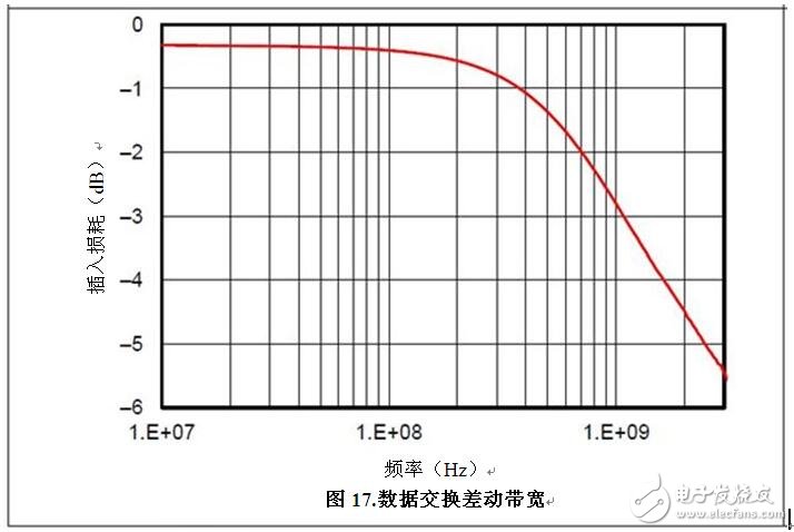
Figure 1: TPD3S714-Q1 Data Exchange Differential Bandwidth
You can use an eye diagram to analyze the effect of line capacitance on bandwidth. Measuring minimum and maximum voltage levels and jitter can expose any problems in USB data line transmission. The high 1GHz bandwidth allows for USB 2.0 high speed applications. A small margin above the 720MHz bandwidth also helps maintain a common clear USB 2.0 eye diagram with a long stay in the automotive USB environment. Figure 2 is an example of a USB 2.0 eye diagram.
  
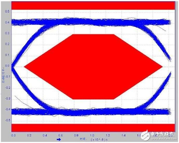
Figure 2: USB 2.0 Eye Diagram of the TPD3S714-Q1
Three-axis stabilizer is composed of pan axis, rolling axis and tilt-axis. With a gyro-stabilized gimbal system, it keeps stabilized or steerable horizon with automatic calibration to give you an unprecedented smooth shooting experience.
3 axis gimbal stabilizer can be divided into 4 parts, including Three-axis Smartphone Stabilizer, three axis micro dslr stabilizer, 3 axis camera stabilizer and 3axis motion camera stabilizer.

For different consumer, there are 2 kind of 3 axis gimbal stabilizer for them, which are consumer stabilizer and Professional Stabilizer.

Wewow focusing on handheld stabilizer is a technology company which does R & D independently. With Wenpod series product released, the company achieved the industry's praise and quickly became the leader of the smart stabilizer industry.
Our service
1. Reply to you within 24 hours.
2. Already sample: within 1-2days.
3. Shipping date: within 24 hours once get the payment.
4. 12 months warranty.
5. After-sales service, solve within 3 working dates.
If you have any questions, please contact with us directly.
Wewow appreciates domestic and international business relationship!
Three-Axis Stabilizer,Popular Three-Axis Mobile Phone Stabilizer,Professional Three-Axis Stabilizer,Handheld Three-Axis Gimbal Stabilizer
GUANGZHOU WEWOW ELECTRONIC CO., LTD. , https://www.stabilizers.pl