Schematic diagram of main and auxiliary windings of single-phase motor
The principle of the electric phase motor, when the single-phase sinusoidal current passes through the stator winding, the motor will generate an alternating magnetic field. The strength and direction of the magnetic field change sinusoidally with time, but it is fixed in the spatial orientation, so it is also called This magnetic field is an alternating pulsating magnetic field. The alternating pulsating magnetic field can be decomposed into two rotating magnetic fields with opposite rotation speeds at the same rotation speed. When the rotor is stationary, the two rotating magnetic fields generate two equal and opposite torques in the rotor, so that the synthesis The torque is zero, so the motor cannot rotate. When we use an external force to rotate the motor in a certain direction (such as clockwise rotation), the movement of the cutting magnetic field between the rotating magnetic field of the rotor and the clockwise rotation direction becomes smaller; between the rotating magnetic field of the rotor and the counterclockwise rotation direction The cutting magnetic line motion becomes larger. This balance is broken, the total electromagnetic torque generated by the rotor will no longer be zero, and the rotor will rotate in the direction of the push.
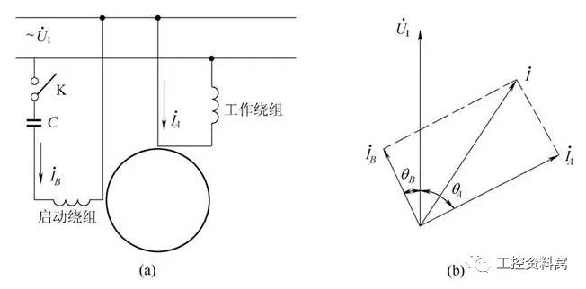
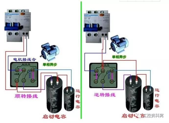
Capacitor split-phase motor wiring diagram and vector diagram
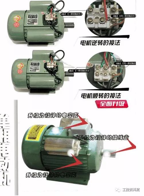
In order to make the single-phase motor rotate automatically, we can add a starting winding to the stator. The starting winding is 90 degrees out of phase with the main winding. The starting winding must be connected in series with a suitable capacitor so that the current with the main winding is The phase is approximately 90 degrees out of phase, the so-called phase separation principle. Such two currents that differ by 90 degrees in time into two windings that are 90 degrees apart in space will produce a (two-phase) rotating magnetic field in space. The schematic diagram can automatically rotate the rotor under the action of this rotating magnetic field. After starting, after starting, when the speed rises to a certain value, the starting winding is disconnected by means of a centrifugal switch or other automatic control device mounted on the rotor, and only the main winding works during normal operation. Therefore, the starting winding can be made in a short-time mode of operation. But there are many times when the starting winding is not broken. We call this kind of motor a single-phase motor. To change the steering of this motor, just change the terminal of the auxiliary winding.
The main and auxiliary windings of single-phase motors basically follow the principle that the main winding impedance is small and the secondary winding impedance is large, which helps to extend the discharge time of the capacitor and enhance the phase shifting effect of the capacitor. We use a multimeter to measure the main The secondary winding is mainly based on this point. For a single-phase asynchronous motor with only three lead wires, the single-phase motor that leads to four wires is generally the two windings that are not inside the motor and is connected to each other. The multimeter is used to determine the primary and secondary windings. as follows
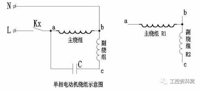
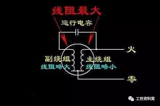
In the first step, use a multimeter to find the two leads with the highest resistance from the three leads. The remaining one is the common lead connected to the main and auxiliary windings. In the above figure, the resistance between the leads a and c is the largest, and the lead b is the common terminal lead.
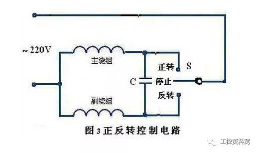
In the second step, the multimeter is used to measure the resistance between the common lead and the other two leads, and the winding connected between the common lead and a lead having a larger resistance is the secondary winding. The winding connected between one of the smaller resistance leads is the main winding. As shown in the figure, the resistance between the leads bc is large, and the lead c is the secondary winding lead. The resistance between ab is small, and the lead a is the main winding lead. For the single-phase motor (washing machine motor) with the same main and auxiliary windings, the switch is used to control the positive and negative rotation.
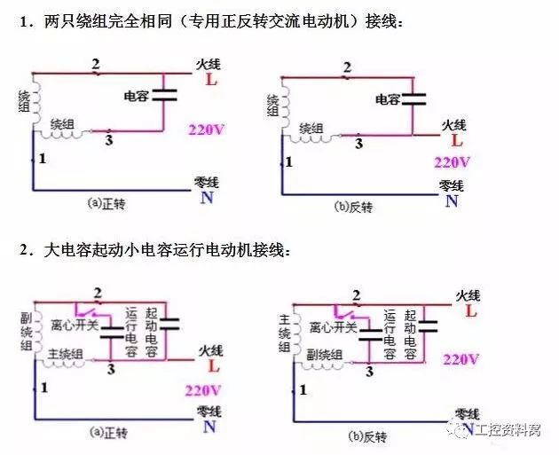

Double capacitor with clutch switch single phase motor
Zhejiang Synmot Electrical Technology Co., Ltd , https://www.synmot-electrical.com