Share the six secrets to overcome the problems often encountered in the RF signal path
Although most RF and microwave test systems measure only a wide range of categories—amplifiers, transmitters, receivers, etc.—each individual system faces a number of different environmental conditions, requirements, and challenge. While each situation may be different, when you are defining any RF and microwave test system, there are three common factors that affect each other: performance, speed, and stability. In the case where each system developer has different conditions, the best choice between these three factors will be related to whether the measurement results can reach the required correctness level.
From the DUT to the path between the measuring instruments (Figure 1), there are many points where the timing of these factors will occur. This paper suggests an architecture that considers these trade-offs and provides six tips for how to overcome RF. Problems that are often encountered on the signal path.
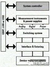
Figure 1: Under all test system architectures, there are many opportunities to strike the best balance between performance, speed and stability to control the correctness of the measurements.
Tip 1: Prioritize efficiency, speed and stability
In order for all six secrets to be discussed, it is necessary to clarify our definition of efficiency, speed and stability. In most cases, only one or two of these factors will be the primary consideration, leading your testing needs and equipment choices. In any case, a careful review of the interactions and trade-offs between performance, speed and stability (listed in the summaries in Tables 1 through 3) will help you control the unique needs situation.
Basic definition
In RF and microwave test equipment, the definition of "performance" by technology mainly refers to the accuracy, measurement range and bandwidth of the instrument. The accuracy of the instrument includes the absolute accuracy of the specified amplitude and frequency measurements; the measurement range refers to the dynamic range, distortion, noise level and noise, which affect the accuracy of the signal level measurement; and the bandwidth It refers to the frequency width or data rate that can be processed and analyzed. The speed test system's speed or Throughput will depend on the hardware used, the input/output (I/O) interface, and the software. Our focus will be on the hardware and four factors that affect speed: measuring set time, Measurement execution time, data processing time, and data transmission time. At RF and microwave frequencies, a very important part of the settling time is the settling time required by the DUT or test system after each change (eg switch on or off, power level change). .
Stable Consistency For any test system, it is important that each test and daily test produce consistent results. However, good stability does not mean high accuracy, because accuracy depends on the performance of individual instruments, and stability means that the measured results are consistent regardless of the accuracy of the specified order. For each instrument, stability may vary depending on certain measurements or modes, so it is important to look at the product specifications or ask the manufacturer. In some cases, stability can be improved by averaging more times, or by modifying the algorithm to accurately approximate the results obtained by the standard measurement method. Minimize the number of changes in measurement settings (such as center frequency, span, and attenuation level) for optimal stability.
An overview of the relationship between the three
DUT's testing requirements and commercial considerations can help you assess the relative importance of performance, speed and stability. Once you have established the primary considerations and the level of requirements, it is easier to figure out the relationship and Its impact on the system. Tables 1, 2, and 3 are for two situations: the requirements for the primary considerations are high or low, and the summary organizes the relationship between them.
Stability and effectiveness
In Tables 1 and 3, there is an important second-level relationship between stability and performance, which is an indirect relationship posed by measurement uncertainty. In the face of uncertainty, some system developers will design an "error budget" whose size depends on the difference between the test requirements and the system uncertainty. The two main factors affecting uncertainty are absolute accuracy (instrument performance) and measurement consistency (stability). If the instrument in the system has a high absolute accuracy, then there is a large amount of error in the error tolerate lower stability. If the instrument can provide consistent results, there will be more room in the error amount to tolerate lower absolute accuracy.
Many requirements are "high"
To meet the multiple requirements of “high speed and high stability†or “high performance and high speedâ€, it may be necessary to use sophisticated and sophisticated instruments, which are naturally slightly higher in price than those with lesser capabilities. However, many high-performance instruments may be built-in to speed up time-consuming tasks such as averaging calculations and calibration. Some models may also contain multiple algorithms that can calculate parameters such as adjacent channel power (ACP). If all three requirements are "high", you must carefully inspect every part of the system - test equipment, switching subsystems, cables, connectors, etc. The best solution is probably not cheap, but it offers some extra features and benefits.
Tip 2: Examine the nature and characteristics of the DUT
An automated test system can perform three basic tasks: providing a signal source, performing measurements, and switching, as to which signal generator, power meter, analyzer, network analyzer, switch matrix to use. And cable, depending on the electrical and mechanical properties of the DUT. At RF and microwave frequencies, there are some basic features that require special attention.
Electrical parameter
The basic nature of the DUT is the main consideration: is it passive and linear, or active and non-linear? Passive linear components are easier to handle because their gain and phase offsets are generally fixed at all allowed input power levels over the entire operating bandwidth. Conversely, active components require extra caution because they typically have a non-linear working area that is quite sensitive to input power and can produce different results at different levels.
As a result, it may be necessary to add an amplifier or attenuator to the test system to precisely control the power level, and perhaps add a coupler to separate the power levels input to the DUT and verify that they are correct. These extra things must not be neglected: at high frequencies, each system component has a complex value (with S-parameters), and each additional connection may have an unwanted interaction with the DUT.
Avoid mismatch: impedance of any cable does not match
Both may cause injection loss, and some power of the signal source or measurement signal is lost. It is well known that power is very expensive at high frequencies and can become more expensive if it is necessary to provide the required power over a wide frequency range. Tip: Use highly accurate cables and accessories, and use a vector network analyzer (VNA) to fully measure the actual impedance of cables and accessories, especially if the DUT is the active component.
Minimize VSWR
The combination of the switching matrix plus its connectors, internal and external cables, and even the bend radius of any RF cable may cause errors due to the voltage standing waves of the DUT. Tip: To minimize this error, you can use a switching matrix with a voltage standing wave ratio (VSWR) specification of 1:2:1 or better.
Increase isolation
If your test requires simultaneous measurement of high and low level signals, the isolation matrix specification will affect the accuracy of the measurement. Tip: If there are many lines through the DUT, you can use a signal generator and a spectrum analyzer to measure the isolation characteristics as much as possible. If this is not possible, the system should be able to route high and low level signals to non-adjacent paths or to different switches during configuration and setup.
Institutional attribute
Another set of details to consider is the number and type of signal and (AC or DC) connectors, which can affect the size of the switching matrix required, as well as the complexity of the system wiring. Tip: Use a sufficient number of switching matrices to connect all connections from the system to the DUT at a time, so that the delay time required to stabilize the wait signal is minimized and the power level is suddenly changed and corrupted. The probability of switching matrices or DUTs is minimized.
Tip 3: Understand, measure, and correct the characteristics of the RF signal path
Without additional corrections, the product's specifications can only be extended to a "calibration plane" located on the instrument's input and output connectors. To get accurate and consistent measurements, as well as corrected DUT results, we recommend extrapolating the calibration surface as close as possible to the DUT. Whether the path is passive or active, the DUT is at the local or remote end, there are several ways to do this.
Passive path processing
The component has a fixed gain and phase offset for all allowed input power levels over the entire bandwidth. However, there may be impedance mismatches on each of the wires that are connected along the passive path, resulting in injection loss and phase offset (or delay). At high frequencies, even simple passive elements can become complex transmission line elements, and the loss and phase offset on the path cannot be directly added by simple algebraic methods. Tip: Use VNA to measure the entire connected path or analyze the S-parameter characteristics of each element and use vector studies to simulate the total loss and phase offset of the entire path. These values ​​can be stored in the system's PC and applied as needed to correct the measurement results, or for use by network analyzers, such as to instantly adjust filters and other changing DUTs.
Correct active path
The performance of the active components will vary with input power. To improve the accuracy of the measurements, the approach will depend on the component operating in its linear or non-linear response region. If an active component (such as an amplifier) ​​is operating in a linear region well below its 1 dB compression point during calibration and measurement operations, accurate corrections can be made at any power level within the zone.
Tip: If the active component is operating in its non-linear response region, the power level for the measurement must also be used during calibration to ensure accurate corrections are made. If it is necessary to measure at multiple power levels in non-linear mode, it must also be calibrated separately at each level and stored for later use.
Tip: Check the active components in the frequency range of the DUT. Similarly, you should measure the entire path at a specific power level, or analyze the S-parameter characteristics of each interface and use vector theory to produce a model that can be applied afterwards or applied immediately.
Tip: In order to simplify the task of measuring and correcting RF signal path characteristics, some system developers will use active components as little as possible, which can reduce the time required for calibration and the power level change when working in nonlinear mode. The opportunity for error.
DUT distance - near or far
Whether the DUT is fixed to the fixture of the test system or in a test room a few yards away, accurate corrections can sometimes be difficult. Measurements fixed to the fixture are challenging because the path typically involves switching from a coaxial cable to a microstrip based short circuit, open circuit, and load. Tip: If you can't use high-quality microstrip components, you'll need to use a network analyzer to measure fixtures, simulate impedance, and eliminate those effects from your measurements. When the DUT is at the far end, the main problem is the path attenuation caused by the long cable distance and the path difference caused by temperature changes and cable bending.
Tip: If possible, measure the entire path between the instrument and the DUT, or measure each relevant element on the path, and use vector theory to combine its complex response values ​​to analyze the extent of path attenuation.
Tip 4: Don't neglect all the things connected to the instrument
When setting the performance specifications of each instrument, the equipment manufacturer will only provide specifications for the connectors for the supply and measurement signals on the panel. From the beginning of the joint, all things that appear between the instrument and the DUT may affect the stability and consistency of the instrument's performance and measurement. At the frequency and power levels of RF and microwave, there are usually three major culprit: cables, switches, and signal conditioners.
Choose the right cable type
When setting the specifications for your test system, decide which cable to use to connect the devices, and you may also specify the type of switch matrix to use. The general rule is that a stable cable has a lower injection loss and a better VSWR, so the stability and consistency of the measurement is higher. At high frequencies, the three most commonly used cable types are: Semi-rigid, flexible and flexible cables.
Semi-rigid cable
As the name implies, this cable does not easily change shape, ensuring excellent performance and stability. High-quality semi-rigid cables can be manufactured with higher temperature stability by applying MIL-compliant temperature cycling. By using the temperature cycle stimulation method after the forming step, the internal pressure can be eliminated and the formed cable can be prevented from being deformed in the future. The quality of the dielectric used in these cables also affects the performance of their measurements.
Solid Teflon is the most commonly used, but it causes injection loss. Expanded Teflon is currently the best alternative to provide low injection loss and a wide frequency range. This attention to detail is reflected in the cost of these cables, which are much more expensive than soft or flexible cables.
Flexible cable
Such cables are less stable than semi-rigid cables because they are easily shaped and reshaped, and such flexibility can affect the stability of the measurement and long-term reliability.
Flexible cable
Sometimes referred to as "test instrument grade cable", it usually provides good phase stability and low injection loss, but at a relative price. This type of cable has a high maintenance requirement and requires extra care when it is used. Otherwise, severe deformation may change its electrical characteristics, resulting in inaccurate measurement results.
Avoid switching related issues
Switching is important to the operation of the overall system function, automating the signal and power supply connection between the instrument and the DUT. Since most of the signals used as signal sources and those that need to be measured pass through the switching matrix, any lack of specifications may affect the performance, speed and stability of the measurement. At high frequencies, three specifications are particularly important: isolation, VSWR, and injection loss.
Expanding isolation
When there are one or more high power signals, leakage between signal paths can make measurement of low power signals extremely difficult. (This is most likely to occur when high power and low power signals are simultaneously passed through a switching matrix.)
Tip: Choose a switch with an isolation specification of 90 dB or better, which reduces leakage and may not require routing signals around different switching components.
Lower VSWR
A high VSWR can cause phase errors, thus affecting the accuracy of vector and modulation measurements. The VSWR of the switching matrix is ​​directly related to the VSWR of the coaxial switch used in the matrix, and the VSWR of the individual switch depends on its mechanism size and tolerance.
Tip: You can further reduce the VSWR by using a cable that is shorter than the desired bandwidth. If the short cable cannot be used because of the high bandwidth requirement or the requirements of the mechanism, the best alternative is to add the injection loss to the transmission line through the loss pad or the lossy cable, so that you can think about it. The desired frequency range reduces the amplitude of the chopping caused by VSWR, but at the expense of higher overall injection loss.
Control injection loss
At higher frequencies, injection loss tends to become a problem, and its specifications are usually set in the form of tables or equations relative to frequency.
Tip: As the switch ages, the injection loss may change, so pay attention to specifications such as "stability of injection loss" or "stability of injection loss". The validity of this specification can be continued until the product is expected. When the service life expires. Understanding the worst-case loss values ​​can help control the amount of error.
Evaluation signal transformer
As described in Tip 3, the DUT, its test requirements, and its location determine whether a passive or active signal transformer is to be added to the signal path. The whole waver can be an independently operated device or built into the switching matrix. Amplifiers, attenuators and frequency converters are the most commonly used signal shaping components.
Amplifier
If accurate amplitude measurements are required, or if the signal is transmitted over a long cable, additional signal gain may be required. There are several important specifications that can help determine if the amplifier you are using is suitable.
VSWR
The most notorious problem with amplifiers is the poor VSWR.
Tip: Connecting an attenuator or isolator (although the bandwidth of the two is limited) to the output of the amplifier can alleviate the VSWR problem.
Interactive modulation
The bandwidth of the amplifier is important when measuring cross-modulation distortion or side-by-side emission noise outside of the DUT bandwidth.
Tip: Beware of amplifiers with poor dynamic range or very low 1 dB compression points, because if there is a strong fundamental signal, this amplifier will cause interactive modulation distortion that can affect the harmonic measurement results.
Clutter (spur)
Switched power supplies can generate clutter associated with switching frequencies (typically 100-200 kHz).
Tip: Avoid using amplifiers or any other components that contain a switched power supply.
Attenuator
Electromechanical and electronic designs provide varying degrees of flexibility and precision in managing signal levels. The electromechanical attenuator uses a splitter with a typical step resolution of 1 or 10 dB. The electronic attenuator provides an almost continuous setting with a resolution of 0.1 or 0.25 dB; however, an attenuator with a PIN diode switch may generate spikes sufficient to cause "video leakage", while affecting The result of the measurement.
Tip: Connect electromechanical and electronic attenuators as needed to provide better attenuation control.
Tip: Pay attention to the plating materials used on the attenuator connector. For example, nickel will become non-linear at high power levels and will cause interchanging distortion, so choose a higher quality connector, such as gold. of.
Transponder
When the DUT is far from the test system, the downconverter can be used to shift the signal to a lower frequency range, thereby reducing the injection loss caused by the cable being too long.
Tip: On the test system side, you can use the upconverter to restore the signal to its original frequency. However, you may also need to add filtering to filter out the excess frequency components generated during the conversion process.
Tip: When performing vector or modulo measurements, if multiple sets of signals, multiple paths, or multiple conversions are used, some form of phase-locking mechanism must be used to ensure accurate results. This is done by connecting the instrument and the transponder to a common frequency reference point and then measuring the phase of each set of signals relative to the reference signal.
Tip 4: Check the switcher's operational properties
When using a technology to switch matrices, in addition to electrical performance, further consideration of operational characteristics, such as service life, power requirements and fail-safe function, will assist you. Make the right choice.
Electromechanical vs. electronic
Electromechanical switches contain a large number of moving parts and physical joints, so it is easy to have a problem of relatively fast deterioration of quality, which will reduce its stability and shorten the limited life. Conversely, the electronic switch has no mechanical parts that can move, so it has a long service life and higher stability. In practice, which one should be better? Some factors depend on the number of toggles the system actually needs: factors such as the number of closures per test, the number of tests per day, and the expected life of the system.
Another practical consideration is the power level of the signal being wound. Switching high-power signals can damage most switches, reduce stability, and shorten service life.
Tip: To prevent the life of an electromechanical or electronic switcher from ending early, you can set the system's instrument to lower the level of the signal before turning any of the switches in the matrix on or off.
Self-locking vs. non-latching
Self-locking or non-self-locking relays are used inside the electromechanical switch. Most self-locking relays require a 100-200 msec DC power pulse to turn the relay on or off. In order to minimize power requirements, some developers will set the system to turn them on sequentially or in small batches (although this will extend the total switching time). A non-self-locking switch requires a fixed power supply, typically 24V at 200 mA, to maintain contact contact. In a large switching matrix, non-self-locking switches may generate enough heat in the system rack to affect measurement performance.
Tip: If you choose to use a non-self-locking switch, check the actual temperature rise and be mentally prepared: additional cooling units may be added to the system rack.
Tip: It is important to understand the behavior of these two switches after a power outage or emergency power outage. For maximum security, you can choose to return to a known state or set switching matrix when power is restored. Non-self-locking switches are often preferred for fail/failsafe because they open when the power is interrupted and do not close until the test program is powered. However, if the self-locking switch is included in the hardware and hardware of the safe mode when the power supply is interrupted, it can also have the safety protection capability in case of failure or failure.
Advanced features: built-in signal transformer
One of the benefits of using a switching matrix in a system is that the signal shaping function can be built into the matrix by the manufacturer. For example, Agilent's custom switching matrix can be configured with a variety of components: amplifiers and attenuators; filters and isolators; and phase-in and trans-frequency components such as mixers, doublers and (doubler) Divider). These components are fixed connections using semi-rigid coaxial cables and do not require additional wiring to provide a compact, convenient stand-alone solution.
Tip 5: Speed ​​up measurement setup and execution speed
Evaluate system performance based on the number of DUTs tested per unit time, the number of tests performed per unit of time, or other time-based metrics. The measurement speed depends on two basic criteria. Factors: The time required to set up the system, and the time required to perform the measurement. The three major components of all systems - hardware, I/O, and software - can be a boost or resistance to both operations.
Fine-tuning individual instruments
All settable devices used in the system may become bottles that limit the speed of measurement. The latest generation of RF/microwave instruments - signal generators, power meters, spectrum analyzers and network analyzers - have the flexibility and capabilities to reduce bottlenecks and improve system performance.
Signal generator
Many signal generators have built-in modulation and arbitrary waveform generation capabilities that help reduce the number of instruments that need to be used in the system, simplify system wiring, and reduce software complexity.
Tip: The setting of the instrument may be a bit complicated and time consuming, but it can be stored in the memory by pre-creating some setting states, and then the system can be called to save the state as needed, and the test time is greatly shortened. . If the system needs to load arbitrary waveform data during test execution, just download the minimum number of points and use the binary format instead of the ASCII format.
power meter
The factor that can save the most time may come from the fact that some models offer built-in calibration capabilities that extend the calibration interval from hours to months.
Tip: Try to use a digital power meter that provides a wide video bandwidth and fast data sampling speed. Some of these models can generate 1000 or more corrected readings per second and increase the amount by average. Accuracy and stability of the measurement.
Spectrum Analyzer
For any spectrum analyzer, the three main adjustments include: span, number of points per measurement, and resolution bandwidth (RBW).
Tip: Use the minimum number of points necessary and the widest possible RBW is the easiest way to shorten the measurement time. Use a new generation of spectrum analyzers that automatically speed up as much as possible. For example, when making narrow-range measurements, it will be fast. Fu Liye Conversion (FFT) mode.
Tip: For maximum results, the automatic input range adjustment should be used selectively. When measuring a signal whose amplitude changes rapidly, the automatic range adjustment function may frequently change the setting of the input attenuator and slow down the speed of the measurement. However, if the signal level is low and fairly fixed, the automatic range adjustment function can be used to improve the signal-to-noise ratio (SNR) while reducing the measurement time because it can use a wider span and RBW setting.
Network analyzer
Calibration of VNAs can sometimes be time consuming, especially when you need to manually connect to the standard one by one.
Tip: Agilent's electronic calibration or ECal module automates this process by providing faster, more consistent calibration results for one to four turns with a single connection. This method also reduces wear on test åŸ joints and calibration standards.
Tip: Applying corrections inside the analyzer is usually faster than in an external system controller. Most VNAs allow you to store calibration curves for specific tests and re-call them when needed. One thing to be reminded is that this method is more effective when used in a series of narrower spans than in an ultra-wide measured span.
Future development of test system development
The test system will face some unique challenges, but no matter what the situation, the best direct and indirect trade-offs between performance, speed and stability will help to achieve the correctness of the measurement. When choosing the components of a test system such as instrumentation, I/O connectivity, and software, you also need to strike the best balance between these important trade-offs.
iDealTek-Electronics' high-quality, high-precision DC power supply product line is built on years of production, design and technological innovation with DC power supplies. We have a wide range of DC power supply products, from portable Laboratory AC - DC power supplies to Desktop High-precision DC power supplies, to Rack-mounted and Floor-standing Cabinet-type High-power DC power supplies, as well as Intelligent Programmable DC Power Supplies. The output power covers a wide range from 300W to 2000KW, and the output voltage can reach up to 2000VDC. iDealTek-Electronics` DC power supplies are widely used in laboratories, capacitor testing, battery charging, inverter testing, DC motor testing and various cutting-edge applications.
Thanks to the mature and stable AC/DC topology matched with the rapid and efficient control loop and monitoring feedback loop, our DC power supplies can provide high-precision, low-ripple and fast-response DC output with high stability. Through the flexible and friendly man-machine operation panel equipped on the front panel of the power supplies, setting and programming control of the output voltage and current can be easily realized and the high-precision LED or LCD ensures the intuitive and high-precision output measurement function. At the same time, our DC The power supplies can be equipped with RS232 / RS485 / analog signal interfaces to realize remote control programming and status monitoring of the power supplies.


Our DC power supplies have complete built-in protection functions, such as over-voltage protection, over-current protection, over-temperature protection, etc., to ensure the long-term and reliable operation of the power supplies.

If you have a demand for DC power products, we believe that you can definitely find the suitable DC power products among our DC power supplies family.
AC - DC Power Supplies, AC DC Supplies, AC DC Power Supplies, AC to DC Power Supplies, Switching DC Power Supplies
Yangzhou IdealTek Electronics Co., Ltd. , https://www.idealtekpower.com