Technical Analysis of 808D System of Truss Manipulator
1.1 Project background
Robotic Arm is an automatic operating device that can imitate certain motion functions of human hands and arms, and is used to grasp, transport objects or operate tools according to a fixed program. Manipulators are the earliest industrial robots and the earliest modern robots. They can replace human labor to achieve mechanization and automation of production, and can operate in harmful environments to protect personal safety. Therefore, they are widely used in machinery manufacturing, metallurgy, Departments of electronics, light industry and atomic energy.
Truss Type Manipulator refers to the manipulator that takes the truss guide rail as the movement path, mainly carries out horizontal and vertical linear movement, intersperses between different processing machines in the production line, and is responsible for the grasping and feeding of parts. Truss manipulators can flexibly and organically connect different process units of a production line at a lower cost, and have played an increasingly important role in the domestic industrial production automation reform since 2014.
Compared with a fixed-position manipulator, the truss manipulator has no advantages in movement flexibility and load, but it is better than it can move in a large range.
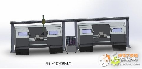
The truss manipulator used in this project is shown in Figure 1. The user workshop is used to connect two grinders, a feeder, and a lathe, for loading and unloading services, forming a production line to produce round tower-shaped auto parts. The requirements for motion control mainly lie in the positioning accuracy of the horizontal X axis, the upper and lower Z axes, and the moving speed. Because the X-axis travel is as long as 8 meters, only high-speed and high-acceleration motion can guarantee the efficiency of parts handling. The design running speed is 90m/min.
1.2 Project configuration
The configuration of this truss manipulator is shown in Figure 2:
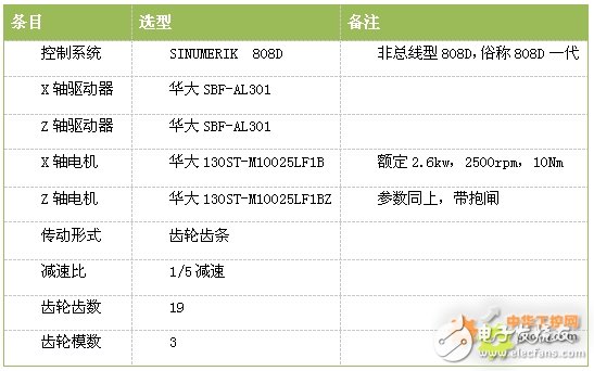
figure 2
The specific parameters of the Huada 130ST-M10025LF1B motor are shown in Figure 3:
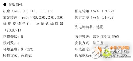
image 3
The design requirement is that the operating speed of the X and Z axes reach 90m/min.
2. Principle analysis2.1 System design limits the maximum speed of the motor
Generally, the speed of the motor follows the formula (1):
N=A*60/B formula (1)
In formula (1), N: the speed of the motor;
A: The frequency sent by the system to the stepper motor;
B: The number of lines of the motor encoder
The highest frequency of the stepping motor sent by the 808D system is set to 333333 in MD31350 (see Figure 4), and cannot be modified. In order to improve the resolution of the motor, the encoder must be at least 2500 lines, and the frequency will be multiplied by 4 in the system. , The maximum speed of the motor can be calculated as
This is also in line with the fact that the maximum speed of Siemens 1FL5 motors is mostly 2000r/min, which is determined by product positioning.

Figure 4
2.2 Transmission calculationGear & Rack (Gear & Rack) is a device that uses the rotation of the gear to convert the rotary motion and the linear motion to each other, as shown in Figure 5. It is divided into straight teeth and helical teeth, so I won’t repeat them.
The amount of movement per revolution of the gear side Lg (M=modulus, Z=number of gear teeth):
The amount of movement per revolution on the motor side Lm (n=reduction ratio):
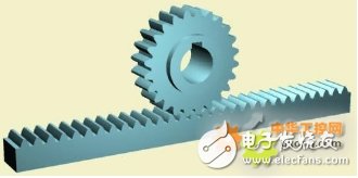
Figure 5
When setting the parameters, the rack and pinion structure is equivalent to the screw structure, then the amount of movement Lg per revolution of the gear side that is affected by the transmission ratio is equivalent to the screw pitch, so the parameter setting is shown in Figure 6:

Figure 6
Motor speed ωm = truss linear velocity Vm that can be achieved at 2000rpm:
Motor speed ωd required for design moving linear velocity Vd = 90m/min:
Therefore, under the existing transmission mechanism, the current motor speed of 2000rpm can only make the truss run up to 71.6m/min at the fastest. The actual situation is the same. The maximum running speed of the truss is clamped at about 70m/min. The 90m/min linear speed required by the design requires a motor speed of at least 2500rpm.
2.3 Control PrincipleWhen SINUMERIK 808D system controls Huada SBF drive, 808D system sends a certain number of pulse signals to the SBF drive according to the processing result of the interpolator, and Huada drive drives the motor to rotate a certain angle, and the shaft advances a certain distance. The number of pulse signals and the corresponding relationship between the rotation angle of the motor are described by the pulse equivalent.
Pulse Equivalency is the displacement of positioning control movement when the controller outputs a positioning control pulse. For linear motion, it refers to the distance moved, for circular motion, it refers to the angle of rotation. For machine tools, the displacement of the moving parts of the machine tool relative to each pulse signal is called the pulse equivalent, which is also called the minimum setting unit.
In the 808D CNC system, the parameter describing this physical quantity is shown in Figure 7:

Figure 7
In Huada SBF drive, the parameter describing this physical quantity is shown in Figure 8:

Figure 8
Thus, in the SBF drive, the 4:1 position command pulse frequency division means: every time 4 command pulses are received, the motor rotates a minimum amount of movement. And what is the minimum amount of movement of the motor? This is determined by the resolution of the encoder. If the accuracy of the encoder reaches 1°, the drive cannot control the motor to go to 4.3°. The encoder of this motor has 2500 lines per revolution, so the number of pulses required per revolution is 2500×4=10000, which is equal to 10000 pulses/revolution set by MD31400 of 808D.
This is very important in the control system. Two devices (same brand/different brands) need to transmit instruction information, no matter what the carrier of the information is or several transmission links in the middle, the most important thing is to ensure that these links and carriers are "consensual transmission", not "Same transmission".
For example: A is a Chinese, B is an interpreter, C is an American, A says a word to B, ask B to translate to C, then the following situations may occur:
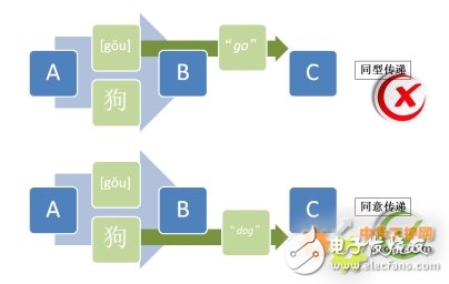
This is why the settings on both sides of the 808D CNC system and the SBF driver must be unified to 10000 pulses/revolution. Only in this way can the position command of the 808D controller be correctly executed by the SBF.
2.4 problem solving
There is no way to increase the maximum pulse output frequency, so if the pulse equivalent can be modified to make the rotation angle represented by each pulse larger, then the 333333Hz pulse can command a faster motor speed.
For the SBF drive, the pulse equivalent can be doubled by setting as shown in Figure 9:

Picture 9
That is: the position command pulse frequency division becomes 2:1: every time 2 command pulses are received, the motor rotates by a minimum amount of movement. In this way, for a motor with an encoder of 2500 lines, a command of 5000 pulses can make the motor make one revolution. The maximum motor speed that can be commanded by the maximum pulse frequency of 333333Hz is given by formula (1):
Meet the control requirements! However, this violates the principle of "consent to pass", as shown in Figure 10:

Picture 10
This will inevitably lead to a system command of 1mm and a mechanical movement of 2mm. So, how to increase the pulse equivalent of the 808D side when MD31400 cannot be changed? My idea is that the motor rotation angle represented by each pulse cannot be changed, but the final movement distance represented by each pulse can be changed. The same effect is shown in Figure 11.

Picture 11
3. Summary of the problem
3.1 Method summary
The final solution is shown in Figure 12:

Picture 12
The idea to solve this problem is to analyze the essence of parameter transfer and find out the substitute parameters of constant parameters.
3.2 Deficiencies
I am worried that it may cause the phenomenon of missing pulses and affect the accuracy. However, after changing the pulse equivalent, the number of pulses per revolution of 5000 is still greater than the number of encoder lines of 2500, so this possibility is very small. Need on-site inspection.
3.3 Site inspection
Through the above parameter modification, the truss axis was smoothly opened to more than 90m/min, and the accuracy problem caused by possible factors such as pulse loss was not found in the long time copying machine.
4. ConclusionSINUMERIK 808D (first generation) limits the speed of the feed axis motor to 2000rpm from both the system and the motor, but in unconventional circumstances, this limitation can also be bypassed, so that the maximum controllable motor speed can reach the theoretical 8000rpm , This usage increases the flexibility of 808D system application. This article aims to introduce the control principle of this truss manipulator project, analyze and summarize the principle and method of the feed axis motor of the 808D system breaking through 2000rpm, and come up with a solution. It may be helpful for engineers who are new to truss manipulators, and in other 808D application cases where the feed motor speed is above 2000rpm.
Shenzhen Kaixuanye Technology Co., Ltd. , https://www.icoilne.com