Telephone remote control 2
Photocoupler
Circuit Operation The child's telephone remote control circuit consists of input amplifier circuit, timer circuit, inverter, oscillation/counter, monostable trigger, decoder, control output circuit and voltage regulator circuit, as shown in Figure 3-153. .
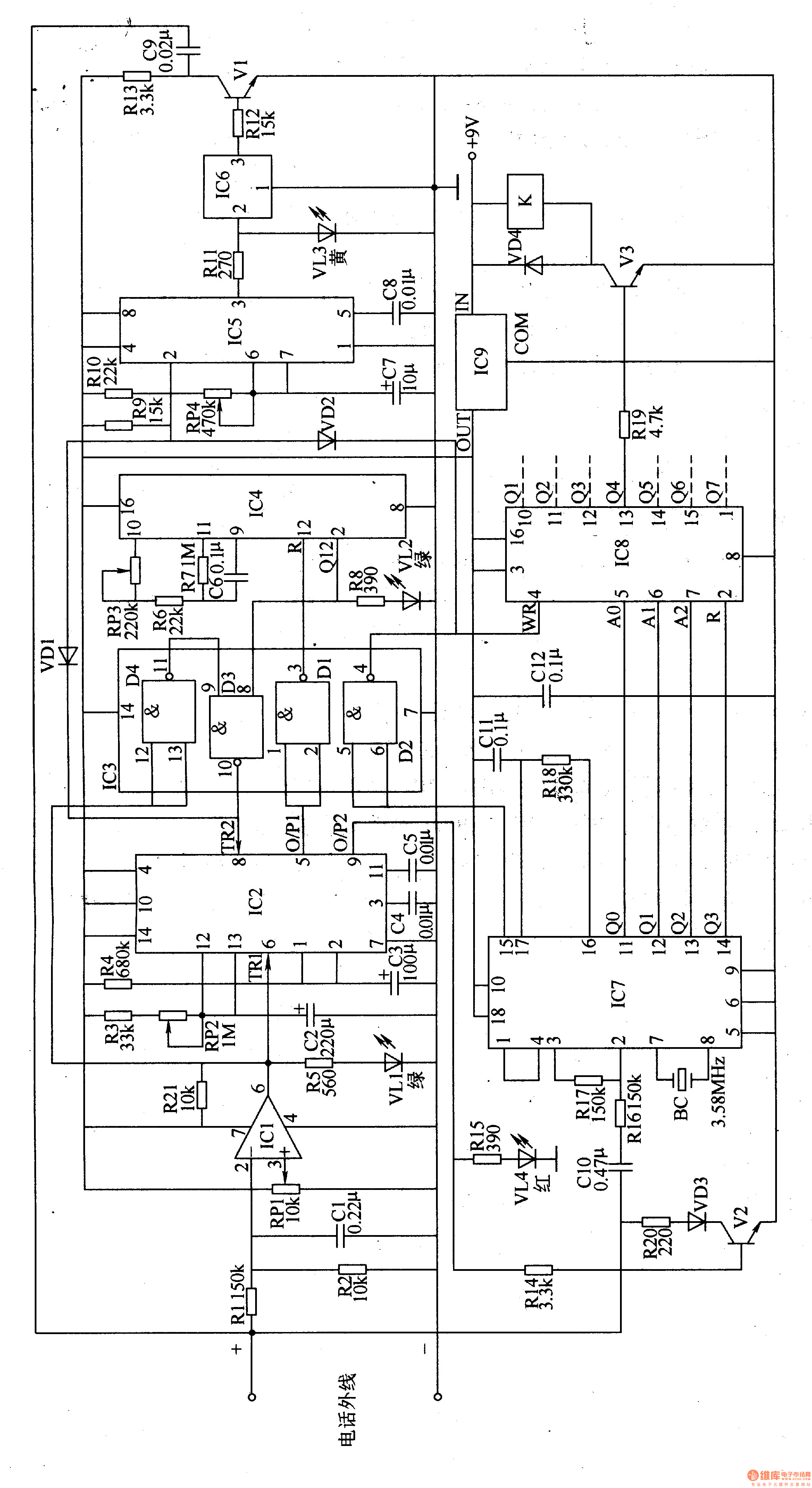
The input amplification circuit is composed of an operational amplification integrated circuit ICl, resistors R1, R2, R5, R2l, a potentiometer RP1, a capacitor C1, and a light-emitting diode VLl.
The timer circuit is composed of a dual time base integrated circuit IC2, resistors R3, R4, a potentiometer RP2, and a capacitor C2-C5.
The inverter is composed of a four-NAND gate integrated circuit IC3 and a resistor R8, and a light-emitting diode VL2.
The oscillation/counter circuit is composed of a 14-bit binary counter integrated circuit IC4 and resistors R6 and R7 and a potentiometer RP3.
The monoflop is composed of a time base integrated circuit IC5, resistors R9, R10, a potentiometer RP4, and capacitors C7, C8.
The music generator is composed of a music integrated circuit IC6, a resistor R11-R13, a light emitting diode VL3, a transistor Vl, and a capacitor C9.
The decoder circuit is composed of an integrated circuit 1C7, resistors R14-R18, R2O, capacitors ClO, C11, a crystal oscillator BC, a diode VD3, a light-emitting diode VL4, and a transistor V2.
The control output circuit is composed of an address latch integrated circuit IC8, a transistor V3, a resistor R19, a diode VD4, and a relay K. Due to space limitations, only one control execution circuit (the fourth control execution circuit composed of Rl9, V3, VD4, and K) is drawn in the circuit. The circuit structure and parameters of the other six control execution circuits are the same as those of the fourth channel. Draw.
The voltage regulator circuit is composed of a three-terminal voltage regulator integrated circuit ICg and a capacitor Cl2. The external +gV power supply is used as the working power supply of relay K; the other is regulated by IC9, and is supplied to lCl-IC5 and 1C7, 1C8.
Connect the telephone remote control to the outside line of the telephone, and use the normally open contact of the relay to control the working power of the controlled appliance. When using, first dial the phone number of the home. When the dial tone is heard, the phone remote control emits a music tone, indicating that the phone remote control circuit is already active and can accept the remote command. Then press the "*" button, then dial any one of the "1"-"7", you can turn on the power of any of the 7-channel controlled appliances; press "*" and then press "8" "The number keys can turn off the power of each controlled appliance.
After the phone is connected, the ringing signal is amplified by ICl to make the flip-flop inside IC2 flip. The high level of the output of pin 5 of lC2 is inverted by the D1 in IC3, and the low-level reset is provided for the 12 pin of l. The signal causes lC4 to start counting the ringing signal. After a delay for a period of time, IC2's 2 pin outputs a high level, and another flip-flop and a monostable flip-flop inside 1C2 are flipped through D3 in IC3, and the 9-pin output of IC2 outputs a high level, so that V2 conducts the telephone outside line. The input voltage drops to 10-12V, which is equivalent to the off-hook listening state; while the high level output of IC5 pin 3 causes VL3 to emit light, IC6 is triggered to work, and the music signal of the 3-pin output is amplified by Vl. Send to the outside line to inform the operator that the remote control is already in the receive input command state. At this time, the operator can press the "*" button to change the telephone signal into the dual audio DTMF signal mode. The DTMF signal generated after dialing the number key "1"-"7" is sent to the AO-A2 end of IC8 after being decoded by lC7; at the same time, the 15th pin of IC7 outputs a high level, and the high level is passed through IC3. After D2 is inverted to a low level, an output terminal of the Q1-Q7 terminal of IC8 is turned to a high level, and the circuit controls the execution circuit.
For example, after dialing the "4" button, the Q4 terminal of IC8 goes high, V3 is turned on, K is pulled, and the power of the fourth device is turned on.
When the operator dials the "8" key, the Q3 terminal of IC7 outputs a reset command to reset IC8, and its Ql-Q7 terminals all become low level, and the power supplies of each circuit are cut off.
Adjust the resistance of RP1 so that the voltage of pin 3 of ICl is about 2V, and VLl flashes when the phone rings.
Adjust the resistance of RP2 to set the available time of remote control action.
Adjust the resistance of RP3 to set the activation time of the circuit.
The resistance of the RP4 can change the music playing time.
Component selection
RI-R21 selects 1/4W carbon membrane resistor or metal membrane resistor for use, R2 selects 1/2W metal membrane resistor for use.
RPl-RP4 uses organic solid variable resistors.
Cl, C4-C6, C8, C9, C11 and Cl2 are selected from monolithic capacitors or polyester capacitors; C2, C3 and C7 are selected from aluminum electrolytic capacitors with a withstand voltage of 16V; ClO is selected from CBB capacitors with a withstand voltage greater than 1OOV.
Both VDl and VD2 use 1N4148 silicon switching diodes; VD3 and VD4 select 1N4007 silicon rectifier diodes.
VLl-VL4 selects ordinary light-emitting diodes of φ5mm.
Vl-V3 selects BC457 or S8050 silicon NPN transistor for use.
ICl selects CA3140E type operational amplifier integrated circuit; lC2 selects NE556 type dual time base integrated circuit; IC3 selects CD401l type four NAND gate integrated circuit; IC4 selects CD4060 type counter integrated circuit; IC5 selects NE555 type time base integrated circuit; lC6 selects UM66 Type three-terminal music integrated circuit; IC7 selects CM8870 type DTMF decoding integrated circuit; lC8 selects CD4099 type address latch integrated circuit; ICg selects LM7805 type three-terminal voltage regulator integrated circuit.
K selects 9V DC relay, its contact current load should be more than 1.5 times of the load current.
HuiZhou Superpower Technology Co.,Ltd. , https://www.spchargers.com