Two typical electric vehicle flasher circuit design
Electronic enthusiasts provide two typical electric vehicle flasher circuits, and give the parameters and specific instructions in the circuit, I hope to help you!
This article refers to the address: http://
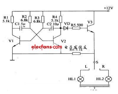
1. This circuit consists of an oscillating circuit and a switching circuit. The oscillating circuit is composed of transistors V1, V2, resistors R1-R4 and capacitors C1, C2. The switching circuit consists of a diode VD, resistors R5, R6 and a transistor V3. The ultra low frequency signal generated by the oscillating circuit is applied to the base of V3 via diodes VD and R5. When the steering switch S is placed at R or L, the V3 ultra-low frequency signal is intermittently turned on, causing the turn signal HL1 or HL2 to flash.
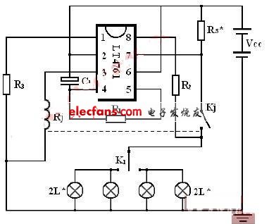
2, 12V flasher circuit diagram:
R1=91K-120K R2=3.0K R3=330Ω Rs*=0.017Ω C1=3.3μ/50υ
Rj, Kj are relays, coil resistance Rj - 100Ω
The L* is a 12v / 21w bulb main chip using the LT4761 automotive flash integrated circuit.
The external circuit can be used interchangeably with the U243B and U2043 models of the overseas model.
Note: The Rs* value should be well adjusted. It will not only affect the voltage usage range, but also the double-flash function. Since Rs* has a small resistance value, it should be appropriately adjusted according to different circuit board designs.
The R1/C1 product determines the flash frequency for normal use, and the R1/C1 value can be adjusted appropriately based on the flash frequency requirement.
9V Ac Dc Adapter,Adaptor 9 Volt,Dc 9V Adapter,9V Ac Adapter
ShenZhen Yinghuiyuan Electronics Co.,Ltd , https://www.yhypoweradapter.com