Wireless charging regulator circuit diagram
A voltage regulator circuit is a circuit that maintains a constant output voltage when input voltage, load, ambient temperature, and circuit parameters change. This circuit provides a stable DC power supply and plays an important role in the stable operation of various electronic devices.
Wireless charging regulator circuitThere are many classification methods for regulated power supply. According to the type of output power supply, there are DC regulated power supply and AC regulated power supply. According to the connection mode of the voltage regulator circuit and the load, there are series regulated power supply and parallel regulated power supply; The working state is divided into a linear regulated power supply and a switching regulated power supply; according to the circuit type, there are a simple regulated power supply and a feedback regulated power supply .
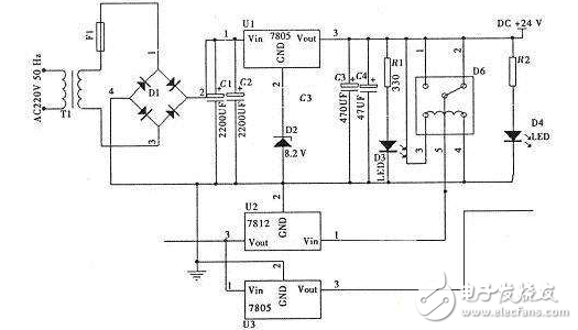
In the wireless charging and transmitting circuit, the power voltage stabilizing circuit uses 7805 and 7812 with D2 voltage stabilizing diode and capacitor and load to form a voltage stabilizing circuit to supply power to the main chip of the transmitter with stable piezoelectricity.
In electronic products, the common three-terminal regulator IC has a positive voltage output of 78 & TImes; & TImes; series and negative voltage output of 79 & TImes; & TImes; series. As the name implies, the three-terminal IC refers to the integrated circuit for this voltage regulation. There are only three pin outputs, which are the input terminal, the ground terminal and the output terminal. The 78/79 series three-terminal regulator IC is used to form the regulated power supply. There are very few external components, and there are overcurrent, overheat and adjustment tube protection circuits inside the circuit, which are reliable, convenient and inexpensive.
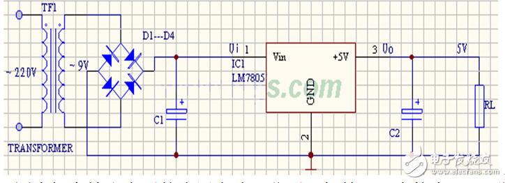
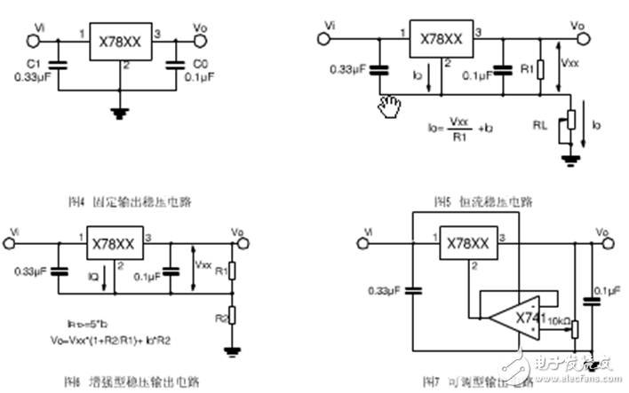
The typical application circuit of the 78XX series integrated voltage regulator is shown in the figure below. This is a regulated power supply circuit that outputs positive 5V DC voltage. The IC uses an integrated voltage regulator 7805, C1 and C2 are input and output filter capacitors, respectively, and RL is a load resistor. When the output current is large, the 7805 should be equipped with a heat sink. The figure below shows the application circuit for increasing the output voltage. The Zener diode VD1 is connected in series between the pin of the 78XX regulator and the ground, so that the output voltage Uo can be improved. The output voltage Uo is the sum of the output voltage of the 78XX regulator and the regulated voltage of the Zener diode VC1. VD2 is the output protection diode. Once the output voltage is lower than the VD1 regulation value, VD2 turns on and bypasses the output current to protect the 7805 regulator output stage from damage.
Other common voltage regulator application circuits:
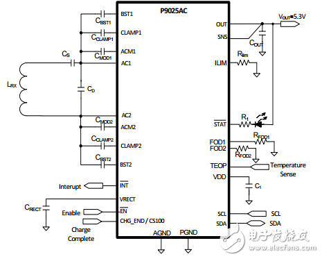
The wireless charging solution of IDT adopts P9025AC power management chip. The chip has many built-in circuits, including voltage regulator circuit, which reduces electronic components, reduces cost, reasonable solution and fast charging efficiency. It can be used for reference.
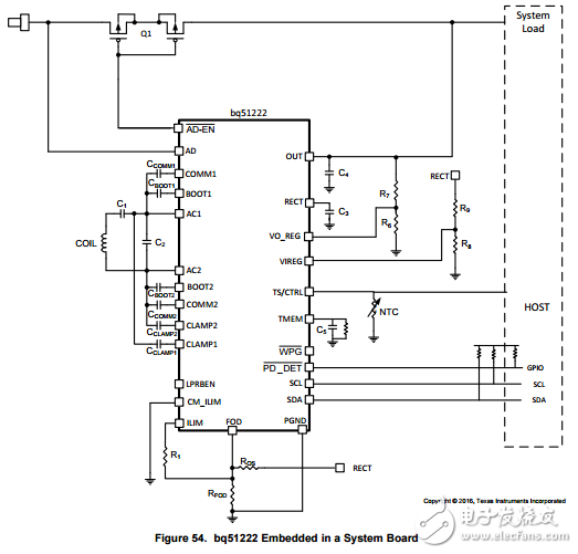
TI wireless charging solution BQ51222, dual mode design (WPC and PMA standard) power supply through the regulator circuit output voltage 5V output maximum current is 1A.
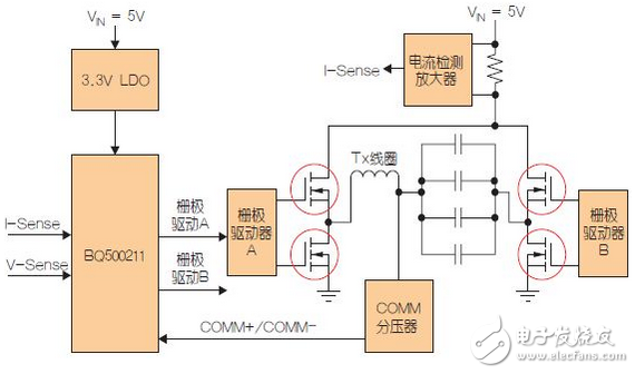
The bq500211Qi transmitter controller has an input power limit option that limits the input current to the transmitter to 500mA, allowing operation via a USB port or a small power adapter. The bq500211 transmitter's voltage regulator circuit has a 3.3V LDO regulator to form the output chip. The biggest advantage of the LDO is that the PNP tube will only bring a small on-voltage drop. The typical drop voltage of the full load is less than 500mV. The voltage drop at the time of loading is only 10 to 20 mV. The dropout voltage of the LDO is: Vdrop = Vsat (LDO regulator).
Grid Fan ,Grid Ceiling Fan,Off Grid Ceiling Fan,Off Grid Fan
Hangzhou Jinjiu Electric Appliance Co Ltd. , https://www.jinjiufanmotor.com