Portable gas detector circuit diagram
The circuit below shows the circuit of the portable gas detector. The dual channel micropower amplifier ADA4505-2 is used in constant potential configuration (U2-A) and transconductance configuration (U2-B). The amplifier's power dissipation and input bias current are very low, making it a good choice for both the constant potential and transconductance sections. Each amplifier consumes only 10 μA, so Battery life is very long.
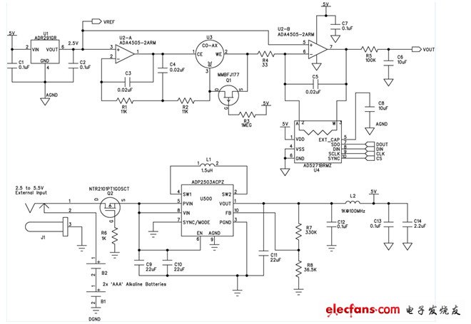
Figure. Portable gas detector using electrochemical sensor
In a three-electrode electrochemical sensor, the target gas diffuses to the sensor and acts on the working electrode (WE) through a thin film. The potentiostat circuit detects the voltage of the reference electrode (RE) and supplies current to the auxiliary electrode (CE) to keep the voltage between the RE terminal and the WE terminal constant. No current flows into or out of the RE terminal, so the current flowing out of the CE terminal flows into the WE terminal, and the current is proportional to the target gas concentration. The current flowing through the WE terminal may be positive or negative depending on whether a reduction or oxidation reaction occurs in the sensor. For carbon monoxide, when oxidation occurs, the current at the CE terminal is negative (current flows into the output of the constant-potential operational amplifier). The resistor R4 is usually very small, so the voltage at the WE terminal is approximately equal to VREF.
The current flowing into the WE terminal causes the output of U2-A to generate a negative voltage relative to the WE terminal. For carbon monoxide sensors, this voltage is typically hundreds of millivolts, but for other types of sensors, this voltage can be as high as 1 V. For single-supply operation, the micropower reference ADR291 (U1) boosts the entire circuit above ground. The 2.5 V.ADR291 consumes only 12 μA; it also provides a reference voltage that allows the analog-to-digital converter to digitize the output of this circuit.
A power inverter, or inverter, is a power electronic device or circuitry that changes direct current (DC) to alternating current (AC).The resulting AC frequency obtained depends on the particular device employed. Inverters do the opposite of "converters" which were originally large electromechanical devices converting AC to DC.
Power Inverter kinds:
1.On grid inverter
2. Off grid inverter
Off Grid Hybrid Solar Inverter,Off Grid Power Inverter,Luminous On Grid Inverter,On Off Grid Hybrid Inverter
NANTONG RONGCHANG IMPORT&EXPORT CO.,LTD , https://www.ergsolarcn.com