Aluminum substrate quick proofing knowledge summary
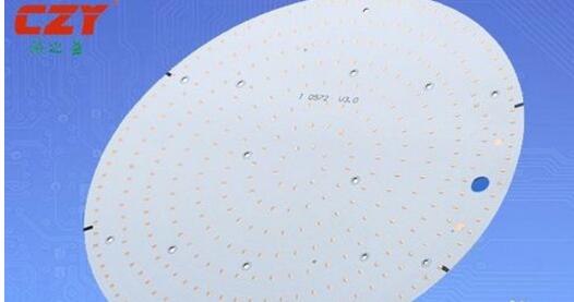
The power device is surface mounted on the circuit layer, and the heat generated during operation of the device is rapidly conducted to the metal base layer through the insulating layer, and then the heat is transferred from the metal base layer to achieve heat dissipation of the device.
Compared with the traditional FR-4, the aluminum substrate can reduce the thermal resistance to a minimum, so that the aluminum substrate has excellent thermal conductivity; compared with the thick film ceramic circuit, its mechanical properties are extremely good.
In addition, the aluminum substrate has the following unique advantages:
Meet RoHs requirements;
More suitable for SMT process;
In the circuit design scheme, the thermal diffusion is processed extremely efficiently, thereby reducing the operating temperature of the module, prolonging the service life, and increasing the power density and reliability;
Reduce assembly of radiators and other hardware (including thermal interface materials), reduce product size, and reduce hardware and assembly costs;
Optimize the power circuit and control circuit combination;
Replaces brittle ceramic substrates for better mechanical durability.
What is aluminum substrate proofingAluminium substrate proofing refers to the use of a photographic method or an electronic color separation machine in the printing process to make a properly tailored negative film. Before large-volume printing, the proof is printed first. The purpose of this is to confirm that the equipment, processes and operations are correct during the printing process and to provide customers with samples that meet the user's needs. Proofing does not require visually the same quality and final product.
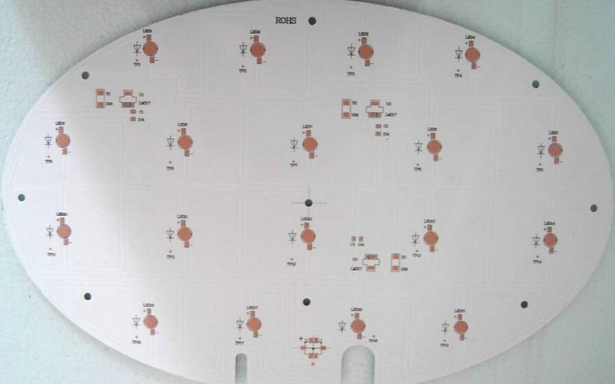
The method of proofing can be divided into two categories. One type is hard proofing, such as mechanical proofing, proofing of photosensitive materials in pre-proofing, and inkjet proofing. The other type is soft proofing, such as screen display.
Mechanical proofing
Machinery is also called analog proofing. Generally, under the same conditions as the printing conditions (such as paper, ink, printing, etc.), the printing plate made from the original printing plate is installed on a proofer, printed, and proofed, and then compared with the original or layout. Proofreading is carried out until the tone, color, text, and layout specifications are correct. Finally, the customer can sign it for printing.
Although mechanical proofing is performed by analog printing, the principle of ink transfer for mechanical proofing, the printed materials used, and the printing environment are often inconsistent with the actual printing. Therefore, the color, reproducibility, and printing of proofs obtained from the proofers on the originals are different. There are always differences in the printed sheets obtained on the machine. In order to reduce this, the difference has now been developed for multi-color automatic proofers and applied in print production. Pre-proofing with pre-proofing method, without the use of printing plates, paper, ink, and proofer, using special photosensitive materials, applying optical, photochemical principles, obtaining color samples or displaying with display screens, problems found in the processing of image information, Corrected in time to improve the efficiency of mechanical proofing.
(1) Photographic material proofing method This method consists of color film lamination, legal color lamination, and electrostatic proofing. The photosensitive material is coated on a film base, and then is attached and exposed with a corresponding color separation and screening film to form monochromatic yellow, magenta, cyan and black films, which are laminated together to form a color image. Also, the colored layer of each monochromatic sheet is transferred onto the proofing substrate to form a color proof sheet.
(b) Computer-assisted proofing This method has soft proofing and hard proofing. Soft proofing, using a computer-assisted color proofing system, sees a color image on the display screen, unable to obtain proofs. Hard proofing, using the data output from the color full page imposition system, to obtain proofs on the hard proofing system. The hard proofing system is generally composed of a display terminal, a keyboard, a floppy disk drive device, a laser recording system, and an online photo developing machine. It is also possible to obtain proofs of the entire page imposition machine through the color ink jet printer.
(C) The electronic proofing method This kind of proofing method mainly adapts to the increasingly developed color desktop publishing system and uses inkjet printers or sublimation printers to obtain proofs. In inkjet printers, the print heads are equipped with fine nozzles that use nozzles to spray ink onto the paper. There are four print heads, three print heads, and one print head. Thermal sublimation printers have a number of thermal elements mounted on the printhead that fuse the transparent dyes on the color ribbons to the paper, and each color overlays each other, overlaying a photo-like color image.
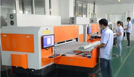
Aluminum substrate proofing process1, open material
Objective: According to the requirements of the engineering data MI, on the large sheets that meet the requirements, cutting into small pieces of production board. Small sheets that meet customer requirements.
Process: big plate → cutting board according to MI requirements → seesaw board → beer fillets → edging → out board
2, drilling
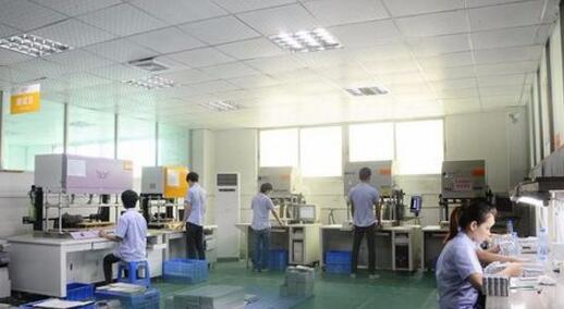
Objective: According to the engineering data, drill the desired hole diameter in the corresponding position on the board that meets the required size. Process: Stacked Pins → Upper Plate → Drilled → Lower Plate → Inspections → Repairs
3, copper sink
4. Objective : To deposit copper on the wall of insulating hole by chemical method.
Process: rough grinding → hanging plate → automatic copper line → lower plate → dilute 1% dilute H2SO4 → thick copper
4, graphics transfer
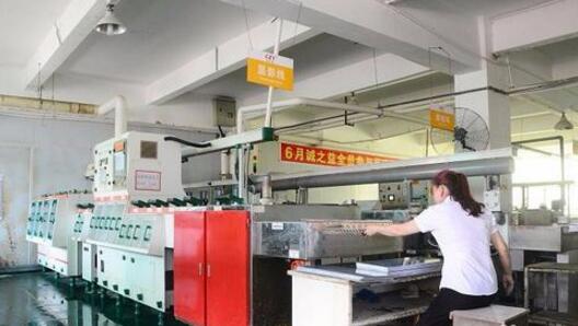
Purpose: Graphical transfer is to transfer the image on the film to the board
Process: (blue oil process): grinding plate → printing the first side → drying → printing the second side → drying → exposure → shadowing → inspection; (dry film process): hemp plate → laminating → standing → pair Bit → Exposure → Resting → Impact → Check
5, graphics plating
Purpose: Pattern plating is to plate a layer of copper to the required thickness and the required thickness of gold or tin on the bare copper skin or hole wall of the circuit pattern.
Process: upper plate → degreasing → washing twice → micro etching → washing → pickling → copper plating → washing → pickling → tin plating → washing → lower plate
6, film removal
3. Objective : To remove the anti - plating film by NaOH solution to expose the non - copper layer.
Process: Water film: insert frame → alkali soak → rinse → scrub → over machine; dry film: put plate → over machine
7, etching
Purpose: Etching is the use of chemical reaction method to etch away the non-line copper layer.
8, green oil
Purpose: Green oil is the transfer of the green oil film to the board, which plays a role in protecting the circuit and blocking the soldering of parts.
Process: grinding plate → printing photosensitive green oil → seesaw plate → exposure → shadowing; grinding plate → printing first side → baking plate → printing second side → baking plate
9, characters
Purpose: Characters are an easy-to-identify marker
Process: After the end of the green oil → cooling stand-by → transfer → print character → rear
10, tin plate (a process of juxtaposition)
Purpose: Spray tin is sprayed with a layer of lead and tin on the exposed copper surface that is not covered with solder resist to protect the copper surface from corrosion and oxidation to ensure good soldering performance.
Process: Micro-etching → Air drying → Preheating → Rosin coating → Solder coating → Hot air formation → Air cooling → Wash air drying
11. Forming
PURPOSE: To use the method of molding or molding the shapes required by the customer by die stamping or numerically controlled crucibles. Organic crucibles, beer board, hand picks, hand cuts
Explanation: The precision of data-board and board is high, followed by hand-rolling. The minimum amount of hand-cutting board can only be done in some simple shapes.
12, test
Objective: To detect defects such as open circuit and short circuit which are not easily detected by electronic 100% test.
Process: Upper mold → put plate → test → qualified → FQC visual inspection → failed → repair → back test → OK → REJ → scrap
13, final inspection
Objective: Through 100% visual inspection of the appearance of the board defects, and minor defects repaired to avoid problems and defective plate outflow.
Specific workflow: incoming → view data → visual inspection → qualified → FQA spot checks → pass → packaging → unqualified → processing → check OK
With the improvement of people's quality of life, people's lifestyles have also become varied. Different kinds of recreational products are starting to appear in people's lives, such as electronic cigarettes. The emergence of e-cigarettes represents a part of young people's thinking and means that electronic products are beginning to show a trend towards diversity.
simply replace the pods. The Pod system uses an integrated pod rather than a tank for higher nicotine strength and provides low power traction. the Pod system is rechargeable and has a longer life and higher battery capacity than disposable electronic cigarettes.
Our company Pod system has a built-in 380mAh battery and a USB charging port on the bottom. In comparison, the Pod system has a built-in battery of only 180mAh, but the Pod system charges much faster.
Our electronic cigarettes are of rechargeable construction. The first time you use the charger to charge, it is recommended to use up the remaining power before filling up, this is to ensure the performance of the battery.
Vape Pod System Oem,Vape Pod Oem,Close Pod Oem,Thc Pod Disposable
Shenzhen MASON VAP Technology Co., Ltd. , https://www.e-cigarettefactory.com