Remote Rehabilitation Information Acquisition System: Can Collect 3D Visual Information in Real-time and Remotely
Tele-rehabilitation is a multi-disciplinary project that combines modern information and communication technologies with rehabilitation medicine. It can be defined as: based on the integrated use of communications, remote sensing, remote control, computers, and information processing, etc. Remote rehabilitation medical service.
The starting points of research in this area abroad are different. To sum up, the long-distance rehabilitation system is mainly used as a means of communication to eliminate space obstacles between assistive device appraisal experts and remote disabled people, and how to treat the remote rehabilitation system itself. As an auxiliary device for evaluating diagnostic systems and promoting the development of rehabilitation medicine, although it has been mentioned, no substantial research has been done. Domestic products in this area only report on the nation’s first long-distance rehabilitation system for disabled persons developed by Shenzhen Disabled Persons’ Federation. The system focuses on communication and exchange between experts and patients, enabling disabled persons to consult with experts on the Internet. , get advice on rehabilitation.
Judging from the current development situation at home and abroad, the research of all parties has greater limitations and both are at the initial stage. Therefore, it is of great significance to study the long-distance rehabilitation system.
In the long-distance recovery system, the information acquisition system is its main component. How to remotely control the information acquisition system effectively, the advantages and disadvantages of its realization effect, the speed of realization, play a key role in the performance of the entire system. Since the remote rehabilitation information acquisition system is a multi-variable and nonlinear time-varying system, it is difficult to establish an exact mathematical model of the entire synchronous control system. Therefore, it is necessary to use an effective control method - fuzzy control.
2 Composition of remote rehabilitation information collection control systemRemote rehabilitation information acquisition control system diagram shown in Figure 1. The system is an assisted camera robot that can accept commands to observe a patient with a space curve. This control system is mainly realized by two functional modules. First, the PC at the on-site site receives the remote station's control commands through the Internet. After being processed by the fuzzy control algorithm, it is transmitted to the single-chip processing system through the RS 232 serial port to control Car, PTZ, camera movement. In addition, the on-site PC can also process the image information collected from the camera according to the requirements, and then present it to the remote site through the Internet in an appropriate manner for the remote rehabilitation expert and auxiliary design manufacturer to diagnose and design. The second is the SCM control system, which is mainly used to control the movement of the dolly, pan tilt, and camera so that it can reach the right position so that the remote rehabilitation expert can observe the patient's physical status in real time, without time and space limitations, and perform remote diagnosis and assessment. The SCM control system can also process signals such as sensors that detect the presence of a motor, and feed feedback to the remote site to control the execution of the fuzzy control system. In simple terms, this fuzzy control system mainly realizes the automatic control of the movement of the trolley loaded with the information acquisition device, the pan and tilt of the camera that drives the camera, and the acquisition of real-time video or image information according to requirements for the purpose of diagnosis and auxiliary product design.
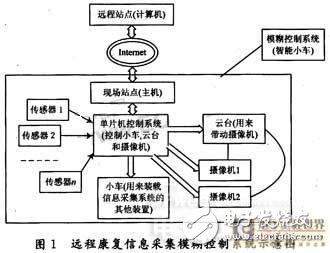
The input variables of the system are: the steering angle from the trolley to the target, the distance from the trolley to the target, the height of the pantograph from the target, and the direction angle and distance between the camera and the target. There are a total of six input variables. The output variables are: the running speed and direction of the car's rudder motor, the running speed and direction of the car's drive motor, the running speed and direction of the motor that drives the pan/tilt up and down, and the four rotations of the pan tilt, altogether 10 output variables. Therefore, the initial control object of the information acquisition system has 6 input variables and 10 output variables, belonging to a fuzzy controller with a multiple input, one output structure.
Through the fuzzy solution, this multi-input multi-output fuzzy control structure is converted to a single-variable fuzzy controller for design. The following describes the establishment of the fuzzy control rule in detail by taking the speed of the drive motor as an example.
The trolley drive motor uses a stepper motor whose speed is controlled by changing the pulse frequency of the drive signal. Therefore, the univariate two-dimensional fuzzy controller is used to control the speed of the drive motor of the vehicle. The input amount is the error e from the trolley to the target distance and the change rate ec from the trolley to the target distance error, and the output variable is the frequency f of the control pulse. In the concrete implementation method of fuzzy control, the fuzzy look-up table method is adopted, and the principle is shown in FIG. 2 .
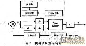
For each sampled error e and error rate change ec for range conversion, which is multiplied by the scale factor k1 and k2, and then quantified, the input physical signal value is converted to the input domain, it can be controlled by query The action table gets the output control amount. It is a point on the output domain, and multiplied by the scale factor k3 for range conversion to obtain the required control pulse frequency value f. The control action table is the corresponding relationship between the point of the input domain and the output domain. It is a process of fuzzification, fuzzy reasoning, and defuzzification that can be calculated off-line. The look-up table method has a simple structure, is easy to implement, has a low resource consumption, and has an online operation speed.
The basic fuzzy subsets of error e, error variation ec, and control amount f are {NB (negative large deviation), NS (negative small deviation), 0 (zero), PS (positive small deviation), PB (positive large deviation)} . In the system, the domain of the vehicle-to-target distance error e is E, the domain of the trolley-to-target distance error rate ec is EC, and the domain of the output control f is F. According to the actual condition of the system, its size is quantified into 5 levels, namely {-3, -1, 0, +1, +3). Select the membership function curve as shown in Figure 3, the controller can complete the input Fuzzing of variables.
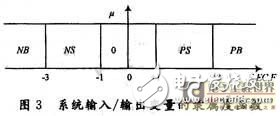
The fuzzy input variables are then inferred by the fuzzy control rules to obtain fuzzy output language variables {NB (negatively large), NS (minus small), 0 (zero), PS (positively small), and PB (positively large)}. In the same way, the output result after fuzzy controller inference must also be converted into the actual correction amount, adjust the pulse frequency of the control car drive motor speed, and complete the control of the car speed.
In order to simplify programming and facilitate real-time control, the system tabulates control rules. The fuzzy controller is controlled according to the control status table shown in Table 1.
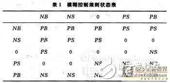
The error E, the choice of the quantization factor k1 and k2 of the error rate EC have a great influence on the dynamic performance of the control system. K1 determines the response speed of the system. The bigger the k1 is, the faster the system responds, but the bigger the overshoot, the longer the transition time. K2 affects the overshoot of the system. The larger the k2 selection, the smaller the overshoot of the system, but the longer the response time of the system will be. K3 is the total gain of the fuzzy controller. If the selection is too small, the dynamic response process of the system will become longer, and if the selection is too large, the system will oscillate.
The control rules for other control variables are similar to those for the control of the speed of the car drive motor described above.
3.2 Software Design of Information Acquisition Control SystemAt present, there are three technologies for constructing the fuzzy controller: using a traditional single-chip microcomputer or microcomputer as the physical basis, compiling the corresponding software to implement fuzzy inference and control; constructing a fuzzy controller with a single-chip microcomputer or an integrated circuit chip and using the configuration data to determine the fuzzy controller The structure of the structure; the use of programmable gate array structure fuzzy controller. Since the remote rehabilitation system site requires a microcomputer to receive remote control commands and process image information from the camera and transmit information over the Internet, we use microcomputers as the physical basis to compile the corresponding software implementations in order to fully utilize and save resources. Fuzzy reasoning and control.
The software design of the fuzzy control PC is mainly the design and implementation of the fuzzy control algorithm. It also includes the serial port communication part of the microcomputer and the microcontroller and the design of the Internet interface. The program flow is shown in Figure 4.
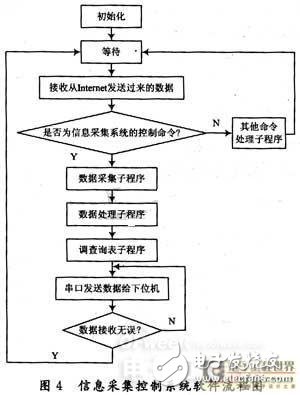
This part mainly realizes the fuzzy control function of the information acquisition system. Before the system is running, the host computer program must be initialized first, set up the serial port, and be ready for the system to run properly. When the remote control command is transmitted to the PC of the on-site site via the Internet, the fuzzy control algorithm is processed, and the command is then sent to the SCM control system via the serial port for execution. This control process does not require the on-site personnel to operate and take full remote control, so that remote experts can conveniently control the operation of the information collection system according to need, and also facilitate the local physicians or patient families, reducing the number of remote experts Operational errors caused by communication barriers with local physicians or family members.
4 ConclusionThe system uses fuzzy control technology to solve the remote intelligent control of remote rehabilitation information acquisition system, so that remote rehabilitation experts and assisted designers can easily remotely control the local information acquisition system through the Internet in an appropriate manner and perspective, accurate, real-time Data collection is performed for diagnosis and auxiliary product design. Experiments have proved that the control system meets our design requirements and can capture 3D visual information remotely and in real time.
Single Phase Control Transformer
Main components
This product is made of high-strength enamelled wire and high-quality silicon steel sheet. BK series transformer core is shell type, which is laminated by silicon steel sheets; BKC series iron core is C-core type.
Technical characteristics
1. BK, BKC and other series of control transformers (hereinafter referred to as transformers) are applicable to power supply for local lighting in industrial and mining enterprises, power supply for control circuits in electrical equipment, and power supply for signal lights and indicator lights in circuits with AC 50Hz~60Hz and voltage up to 500V.
2. The transformer can work for a long time under rated load.
3. The primary and secondary windings of the transformer are separated. When the secondary has only one winding, it bears all the rated capacity of the transformer. If the secondary has both control, lighting and indicator windings, it is wound separately according to the distribution of winding capacity. For the transformer with single winding and intermediate tap, the capacity of each intermediate tap is less than the rated capacity of the transformer, and only the maximum voltage output terminal can bear the rated capacity.
4. The product meets the standard: GB19212.3-2006.
5. Product insulation grade: Class B III.
Environmental conditions editing broadcast
1. The ambient air humidity is - 5 ℃ to+40 ℃, and the 24-hour average value shall not exceed+35 ℃;
2. The altitude of the installation site shall not exceed 2000 meters;
3. The relative humidity of the atmosphere shall not exceed 50% when the ambient air humidity is+40 ℃. There can be a higher relative humidity at a lower temperature. The average maximum humidity of the wettest month is 90%, and the average minimum temperature of the month is+25 ℃. In addition, the condensation on the product surface due to temperature changes shall be considered.
4. Places without violent vibration and impact vibration;
5. A place protected from rain and snow;
6. The voltage waveform is approximately sine wave.
Single Phase Control Transformer,Control Transformer,Isolation Control Transformer,Machine Tool Control Transformer
Henan New Electric Power Co.,Ltd. , https://www.newelectricpower.com