Phosphor selection and solution in LED package
White LED is known as the fourth generation of green lighting source because of its high efficiency, energy saving, long life, no pollution and high reliability. With the steady improvement of LED luminous efficiency and the continuous decline of prices, the current LED light can achieve 150lm/W, and semiconductor lighting will gradually replace traditional lighting sources such as incandescent lamps and ordinary fluorescent lamps.
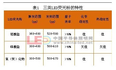
There are two main ways to make white LEDs. One is to use red, green and blue LED chips to package white LEDs, and the other is to use a single LED chip to match phosphors. The latter approach has advantages in production cost, heat dissipation and control circuitry and is most commonly used in industry. Thus, phosphors are one of the key materials for semiconductor illumination. At present, phosphors for LEDs mainly have three major systems, namely aluminate, silicate and nitrogen (oxygen), and their respective characteristics are shown in Table 1.
First, the LED phosphor characteristics of different systems
1. The aluminate system mainly has yttrium activated garnet type phosphors, such as Y3Al5O12:Ce3+(YAG:Ce3+), Tb3Al5O12:Ce3+(TAG:Ce3+) and Lu3Al5O12:Ce3+(LuAG:Ce3+). YAG powder and TAG powder are commonly used yellow powder, LuAG powder is green powder, the quantum efficiency is more than 90%, and has excellent chemical stability and thermal stability. The following is a brief introduction to the crystal structure, spectral properties and thermal stability of the matrix using YAG powder as an example.
Figure 1 is a crystal structure diagram of YAG (cubic crystal system), space group Ia-3d [1]. There are two positions of Al in the unit cell, namely Al1 and Al2, forming AlO6 octahedron and AlO4 tetrahedron, respectively.
2 is an excitation spectrum (a) and an emission spectrum (b) of YAG:Ce3+. In the excitation spectrum, there are two broad-band excitation peaks at around 340 nm and 460 nm, which are attributed to 2F5/2 (or 2F7/2) → 2D5/2 and 2F5/2 (or 2F7/2) → 2D3/ of Ce3+, respectively. 2 transitions. The main peak of the emission is located at 530 nm, which is a broadband emission, corresponding to the 2D3/2→2F5/2 and 2D3/2→2F7/2 radiation transitions of Ce3+ [2]. Suitable for matching white LEDs in blue LED chip packages.
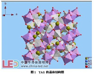
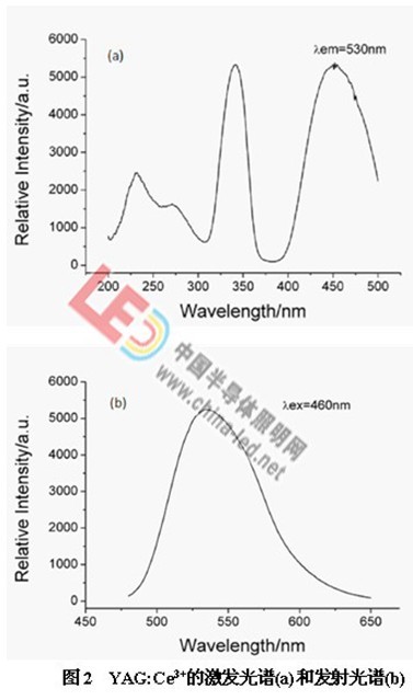
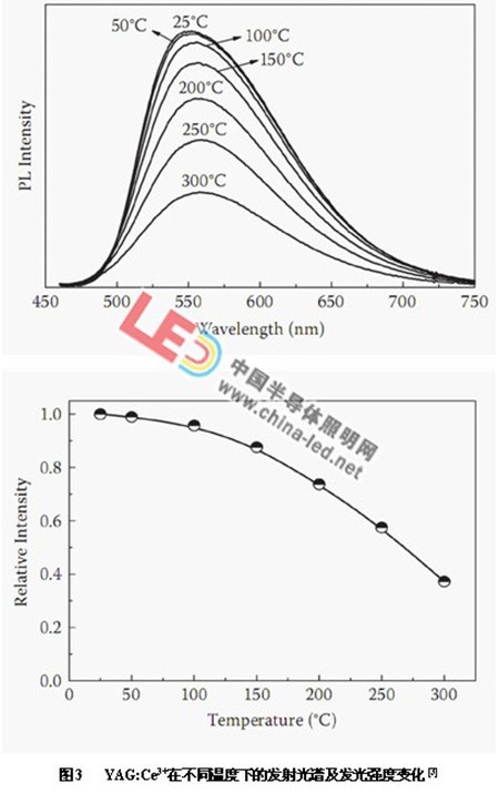
Figure 3 shows the emission spectrum and luminescence intensity of YAG:Ce3+ at different temperatures [3]. It can be seen from the figure that as the temperature increases, the emission peak of YAG:Ce3+ gradually shifts red, and the emission peak intensity gradually reduce. When the temperature is 100 ° C, the emission peak intensity is reduced to 94% at normal temperature. After exceeding 100 °C, the intensity of the emission peak decreases gradually. At 300 °C, the intensity of the emission peak is only 38% at normal temperature.
The superior invention patent for YAG powder and LuAG powder is owned by Nichia, Japan, patent number: US 5,998,925, priority date: 1996.7.29. The patent for TAG powder is Osram (OSRAM), patent number: US 6,669,866, priority date: 1999.7.23.
2. The silicate system mainly has M2SiO4:Eu2+ and M3SiO5:Eu2+ (M=Ca, Sr, Ba) phosphors. The former can be used as green powder and yellow powder, and the latter is orange powder. The chemical stability and thermal stability of such silicate phosphors are relatively poor.
The structure, spectral properties and thermal stability of the matrix are described below by taking Sr2SiO4:Eu2+ and Sr3SiO5:Eu2+ as examples.
Figure 4 is a crystal structure diagram of the Sr2SiO4 (orthogonal crystal system), space group Pmnb [4]. There are two positions of Sr in the unit cell, namely Sr1 and Sr2, which are 8-coordinate and 7-coordinate, respectively.
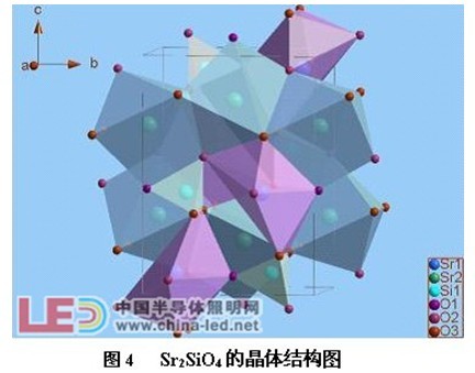
Figure 5 shows the excitation and emission spectra of Sr2SiO4:Eu2+ [3]. The excitation spectrum is broadband from 200nm to 500nm. It can be packaged with UV LEDs, near-ultraviolet LEDs and blue LED chips. The emission peak is a broadband emission centered at 550 nm, which is attributed to the 4f65d1-4f7 transition of Eu2+.
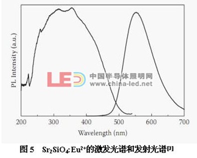
Figure 6 shows the change in luminescence intensity of Sr2SiO4:Eu2+ at different temperatures. It can be seen from the figure that when the temperature is 100 ° C, the intensity of the emission peak drops to about 73% at normal temperature. Further, when the temperature exceeds 100 ° C, the luminescence intensity starts to rapidly decrease, and at 250 ° C, the luminescence intensity is only 8% at normal temperature. It can be seen that its thermal stability is poor.

Figure 7 is a crystal structure diagram of Sr3SiO5 (tetragonal system), space group P4/nccS [5]. There are two positions of Sr in the unit cell, namely Sr1 and Sr2, both of which are 6-coordinated.
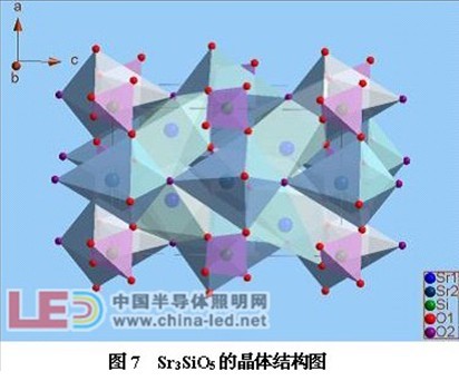
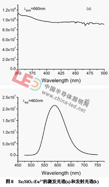
Figure 8 shows the excitation spectrum (a) and emission spectrum (b) of Sr3SiO5:Eu2+. The excitation spectrum covers a range of 350 nm to 500 nm, and thus can be used as a phosphor for ultraviolet LED, near-ultraviolet LED, and blue LED chip. The emission peak is a broadband emission centered at 589 nm, which is attributed to the 4f65d1-4f7 transition of Eu2+. Can be used in combination with yellow powder to increase the color rendering index of white LEDs.