Suppress RFI and EMI with twisted pair and low pass filters
introduction
“The Twist†refers to the twisted pair and Alexander Graham Bell applied for the patent in 1881. This technology has been used today because it provides a lot of convenience. In addition, with the increasing processing power of field programmable gate array (FPGA) devices, combined with circuit simulation and filter design software, the application of twisted pair in the field of data communication is becoming more and more popular.
FPGAs provide design engineers with powerful and flexible control capabilities, especially those that do not have access to application-specific integrated circuits (ASICs), which can be implemented using FPGAs; many high-volume products use FPGAs early in project design. Prototyping and testing new features before customizing the chip. The power of FPGAs is the complex digital processing capabilities, and some analog signals are limited by the interference of digital noise. External analog amplification, as well as offset, filtering, and signal processing are required to ensure that the FPGA meets the overall system requirements.
This article discusses how to combine twisted pair with low-pass filters to suppress radio frequency interference (RFI) and electromagnetic interference (EMI). We also showed how to design a custom differential amplifier with a precision resistor bank to eliminate signal interference and improve the performance of the FPGA system. When we choose the frequency response characteristics, we use a high precision resistor to set the gain and common mode rejection ratio.
The importance of twisted pair
Twisted pair has great significance for data communication, which can significantly reduce crosstalk, RFI and EMI.
The popularity of the Internet and computers has driven the popularity of twisted pair applications. Many people mistakenly believe that twisted pair is a new invention. This is not the case. Figure 1 shows a copy of the patent that Alexander Graham Bell applied for as early as 1881. He described the interaction between multiple pairs of twisted pairs.
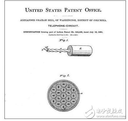
Figure 1. Alexander Graham Bell received US patent 244,426 in 1881
Mr. Bell pointed out that multiple circuits are connected by two wires—a straight-through wire and a return wire—to form a metal wire conductive loop. When the metal line conductive loop is placed near other circuits, if the peripheral circuit senses different signals on the two lines, the telephone and other electrical equipment connected to the metal line will induce an interference signal; obviously, if it is in the straight line and the return line If the same effect occurs, the current generated by one of the wires will cancel the current generated by the other wire. Interference can be avoided if the two conductors have the same inductive relationship to the interference current, or if the two conductors are placed at the same distance as the above circuit (ensuring that the other conditions are identical).
These 125-year-old truths have laid the foundation for modern differential signaling principles. As shown in Fig. 2, the magnetic field generated by the current of the wire A generates an undesired current in the wire B.
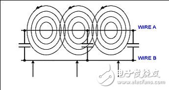
Figure 2. Crosstalk between wires: The magnetic field generated by the current in wire A produces an undesired current in wire B.
The capacitance between the wires in the figure represents the stray-distributed capacitance. When the frequency of the crosstalk signal is increased, the capacitive coupling will be more pronounced. In Figure 3, we observe the “offset†effect proposed by Mr. Bell. When an equal interference signal is applied across the twisted pair, the interference signal will be cancelled. In an RF environment, stray capacitance couples the energy between the wires. Similarly, since the interference of the twisted pair is equal and the direction is opposite, the RFI tends to cancel. Receiving a twisted pair signal in differential form will enhance the "offset" effect.
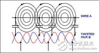
Figure 3. Crosstalk between wires is cancelled when equal interference signals are applied to both sides of the twisted pair.
It is also possible to use a shielded conductor to wrap the twisted pair to provide electrostatic shielding. Shielding increases the stray capacitance and acts as a low-pass filter to further attenuate RF interference. The resistive and inductive properties of the wires are series elements, and the distributed capacitors form a low pass filter to ground. This feature helps improve transmission when the communication link only transmits low frequency signals, such as telephone audio or other narrowband signals.
Connecting Terminals,Micro Connecting Terminal,Aluminum Connecting Terminals,Connecting Copper Terminal
Taixing Longyi Terminals Co.,Ltd. , https://www.lycopperterminals.com