After reading this article, I finally learned the knowledge of ametal_spi and iic bus.
Prof. Zhou Ligong's new book "Programming for AMetal Frameworks and Interfaces (Part 1)" introduces the AMetal framework in detail. By reading this book, you can learn highly multiplexed software design principles and development ideas for interface programming. Focus on your own "core domain", change your own programming thinking, and achieve common progress between the company and the individual. Authorized by Professor Zhou Ligong, from now on, the Zhiyuan Electronic Public Number will serialize the contents of the book, and is willing to share it.
The fifth chapter is to explain AMetal in depth . The content of this article is 5.5 SPI bus and 5.6 I 2 C bus.
5.5 SPI bus
> > > 5.5.1 Initialization
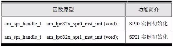
Before using the SPI universal interface, the SPI initialization must be completed to obtain the standard SPI instance handle. The LPC82x supports SPI function with SPI0 and SPI1. For user convenience, AMetal provides instance initialization functions corresponding to each peripheral. See Table 5.10 for details.
Table 5.10 SPI Instance Initialization Functions (am_lpc82x_inst_init.h)
The return value of these functions is the SPI instance handle of type am_spi_handle_t, which will be the argument of the handle parameter in the SPI generic interface. The type am_spi_handle_t(am_spi.h) is defined as follows:

Because the SPI instance handle returned by the function is only passed as a parameter to the SPI generic interface, there is no need to do anything else with the handle, so there is absolutely no need to know about this type. Note that if the value of the instance handle returned by the function is NULL, the initialization failed and the instance handle cannot be used.
If you want to use SPI0, you can directly call the SPI0 instance initialization function to get the corresponding instance handle:

> > > 5.5.2 Interface Functions
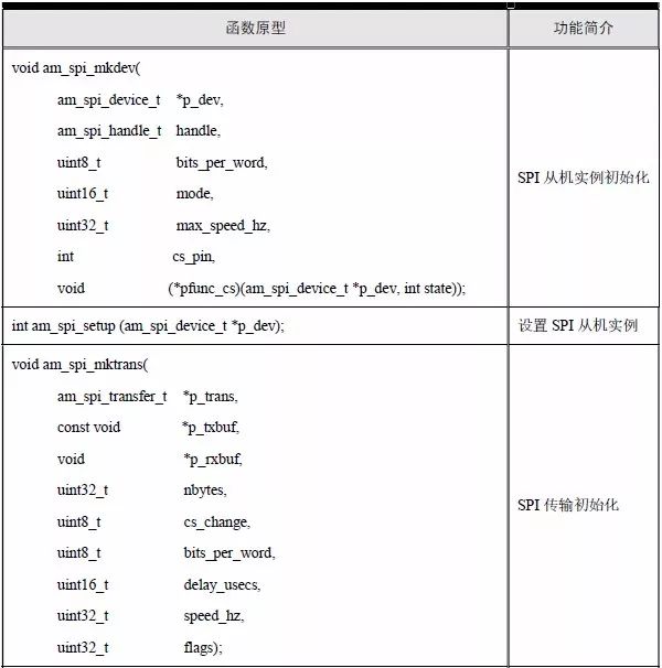
The MCU's SPI is mainly used for master-slave communication, and AMetal provides eight interface functions. See Table 5.11 for details.
Table 5.11 SPI Standard Interface Functions
1. Slave instance initialization
For the user, the SPI is often used to directly operate a slave device. The MCU acts as the SPI master. In order to communicate with the slave device, you need to know the slave device information, such as SPI mode, SPI rate, data bit width, and so on. This requires defining an instance (slave instance) that corresponds to the slave device and using the relevant information to complete the initialization of the slave instance. Its function prototype is:
P_dev is a pointer to the SPI slave instance descriptor, and am_spi_device_t is defined in the am_spi.h file:

This type is used to define a slave instance. The user does not need to know the specific content of the definition. It only needs to define a slave instance with this type. which is:

Mode specifies the mode to be used. The SPI protocol defines four modes, as shown in Table 5.12. The main difference between the various modes is the difference between the idle clock polarity (CPOL) and the clock phase selection (CPHA). Both CPOL and CPHA have two options, so the two-two combination can form four different modes, mode 0~3. When CPOL is 0, it means that the clock line is low when the clock is idle, otherwise it is high when idle; when CPHA is 0, it means the data is sampled on the 1st clock edge, otherwise, the data is in the first 2 clock edges are sampled.
Table 5.12 SPI Common Mode Flags
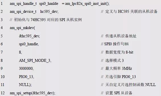
Both cs_pin and pfunc_cs are associated with chip select pins. Pfunc_cs is a pointer to the custom chip select control function. If the value of pfunc_cs is NULL, the driver will automatically control the pin selection control by the pin specified by cs_pin; if the value of pfunc_cs is not NULL, it points to a valid custom chip select. The control function, cs_pin is no longer used, and the chip select control will be implemented entirely by the application. When the chip select pin is required, the driver will automatically call the function pointed to by pfunc_cs and pass the value of state to 1. When the chip select pin is required to be invalid, the function pointed to by pfunc_cs is also called and the value of state is passed to 0. Under normal circumstances, the chip select pin can be automatically controlled, that is, the value of pfunc_cs is set to NULL, and cs_pin is a chip select pin, such as PIO0_13. See Appendix 5.60 for examples of usage.
Listing 5.60 am_spi_mkdev() sample program
2. Set slave instance
When the SPI slave instance is set, it checks whether the MCU's SPI master supports the relevant parameters and modes of the slave instance. If it cannot be supported, the setting fails, indicating that the slave cannot be used. Its function prototype is:

The p_dev is a pointer to the SPI slave instance descriptor. If AM_OK is returned, the setting is successful. If -AM_ENOTSUP is returned, the setting fails, the unsupported bit width, mode, etc., as shown in Listing 5.61.
Listing 5.61 am_spi_setup() sample program
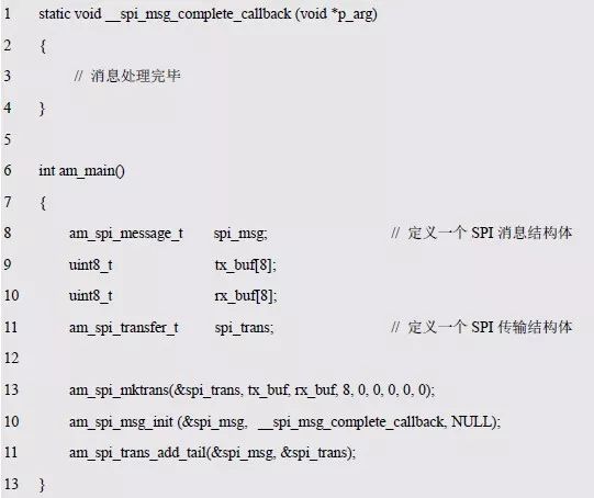
3. Transfer initialization
In AMetal, the process of sending and receiving data is abstracted into a concept of "transport". To complete a data transmission, you first need to initialize a transport structure to specify the information about the data transmission. Its function prototype is:
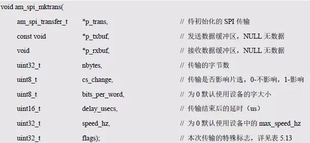
Where p_trans is a pointer to the SPI transport structure and am_spi_transfer_t is defined in am_spi.h. which is:

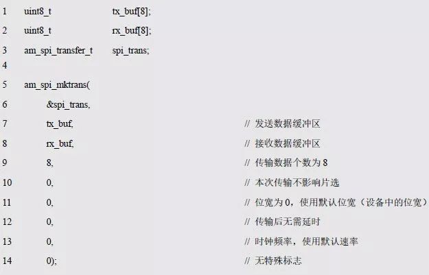
In actual use, only one transport structure of this type needs to be defined. such as:

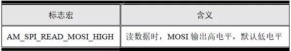
Table 5.13 Transmission Special Control Flags
Because SPI is a full-duplex communication protocol, the transmission and reception of data is included in a single transmission. Among the parameters of the function, p_txbuf specifies the buffer to send data, p_rxbuf specifies the buffer to receive data, and nbytes specifies the number of bytes transferred. In particular, sometimes you only want to transfer data in one direction. If you only want to send data, you can set p_rxbuf to NULL. If you only receive data, you can set p_txbuf to NULL.
When the transfer is normal, the chip select is asserted and the value of cs_change will affect when the chip select is deasserted. If the value of cs_change is 0, it means that the chip selection is not affected. At this time, only when the transmission is the last transmission of the message (multiple transmissions constitute a message, the concept of the message will be introduced later), the chip selection will be Set to an invalid state. If the value of cs_change is 1, it indicates that the chip selection is affected. At this time, if the transmission is not the last transmission of the message, the chip selection will be set to the invalid state immediately after the end of the transmission, if the transmission is a message. The last transmission will not immediately set the chip select to be invalid, but remain valid until the first transmission of the next message begins, as shown in Listing 5.62.
Listing 5.62 am_spi_mktrans() sample program
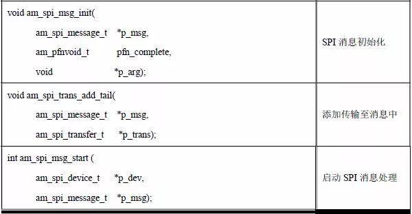
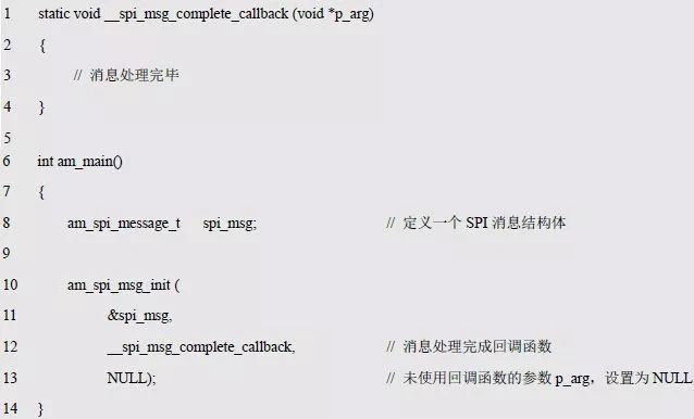
4. Message initialization
In general, when communicating with an actual SPI device, the format of "command" + "data" is often used, which requires two transfers: one transfer command and one transfer at a time. To this end, AMetal proposed the concept of "message". The processing of a message is a meaningful SPI communication, which may involve one or more transmissions.
A message may contain many times of transmission, which may take a long time. To avoid blocking, the message is processed asynchronously. This requires specifying a completion callback function that automatically calls the callback function to notify the user that the message has been processed when the message is processed. The specification of the callback function is done in the initialization function. The prototype of the initialization function is:
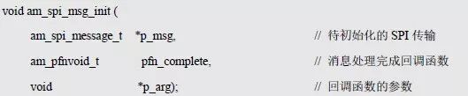
Where p_msg is a pointer to the SPI message structure and am_spi_message_t is defined in am_spi.h. which is:

In actual use, you only need to define a message structure with this type. which is:

Pfn_callback points to the message processing completion callback function, which will call the function pointed to by the pointer when the message is processed. Its type am_pfnvoid_t is defined in am_types.h. which is:

Thus, the function pointer points to a no-return function with a parameter of type void *. When the driver calls the callback function, the parameter of the void* type passed to the callback function is the set value of p_arg, as shown in Listing 5.63.
Listing 5.63 am_spi_msg_init() sample program
5. Add a transfer to the message
A single message is processed in a single message or multiple times. Before the message is processed, the message needs to be associated with the associated transmission. This function is used to add a transfer to the message, the function prototype is:

Among them, p_msg points to the message initialized by am_spi_msg_init(), and p_trans points to the transmission initialized by am_spi_mktrans(). This function can be used multiple times to add multiple transfers to a message. Since the transfer is added at the end of the message each time, the first added transfer is processed first, followed by the post-transfer process, as shown in Listing 5.64.
Listing 5.64 am_spi_trans_add_tail() sample program
6. Start SPI message processing
This function is used to start the processing of the message. The function prototype is:

Among them, p_dev is a pointer to the SPI slave instance descriptor, which is used to specify the slave object that sends and receives data in this message processing; p_msg is a pointer to the SPI message structure that needs to be processed this time. If AM_OK is returned, the startup is successful. When all the transmissions in the message are processed in sequence, the processing completion callback function specified when the initialization message is called; if -AM_EINVAL is returned, the startup failure due to the parameter error is shown. See Listing 5.65 for details.
Listing 5.65 am_spi_msg_start () sample program
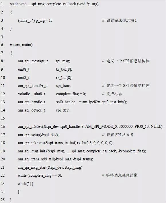
Here, a variable complete_flag with an initial value of 0 is defined. When the message is initialized, its address is used as a parameter of the callback function. Therefore, in the callback function, p_arg is a pointer to complete_flag, and the value of complete_flag can be obtained by the pointer. Modified to 1, if the value of the detected complete_flag is 1, it indicates that the message processing is complete.
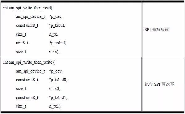
7. Write first and then read
The transmission and reception of data via SPI transfers and SPI messages makes SPI very flexible and supports a wide range of SPI slave devices. But because of its flexibility, it has more interfaces and is more cumbersome to use. For most SPI slave devices, you don't need to be so flexible. You only need to implement simple data transmission and reception. Based on this, AMetal provides two very common situations: reading a piece of data and reading a piece of data. (write first and then read); write a piece of data and then write a piece of data (write twice in succession).
The first write and then read is that the host first sends data to the slave (write), and then receives data from the slave (read). Note that this function will not return until the data transfer is complete, so the function is blocking and should not be called in the interrupt environment. Its function prototype is:
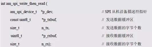
If AM_OK is returned, the data write and read are successfully completed; if -AM_EINVAL is returned, the data write and read failures due to parameter errors; if -AM_EIO is returned, an error occurs during data write or read. See Listing 5.66 for details. .
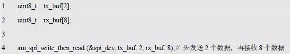
Listing 5.66 am_spi_write_then_read() sample program
8. Write twice in succession
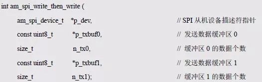
For two consecutive writes, the host first sends the data of buffer 0 to the slave (write), and then sends the data of buffer 1 to the slave (write). If you only need to send data once, you can set the data buffer sent the second time to NULL and set the send length n_tx1 to 0. It is worth noting that this function is also blocking, will wait for two data transmissions to complete before returning, should not be called in the interrupt environment. Its function prototype is:
If AM_OK is returned, the message processing is successful; if -AM_EINVAL is returned, the parameter error causes the data transmission to fail; if -AM_EIO is returned, an error occurs during the process of sending the data. See Listing 5.67 for details.
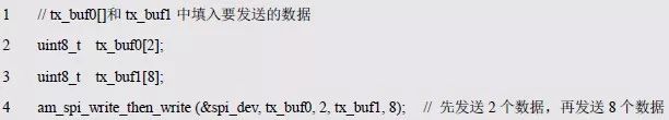
Listing 5.67 am_spi_write_then_write() sample program
> > > 5.5.3 SPI Expansion Interface
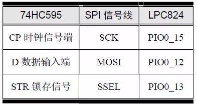
The hardware connection between LPC824 and 74HC595 is shown in Table 5.14. When the 74HC595 is used as the SPI slave, the data only needs to be transferred from the MCU host to the SPI slave without reading data. For the MCU host, the data is transmitted in one direction, and only the data is output without input, so there is no need to use MISO. Obviously, the expansion of the 74HC595 only takes up the SCK, MOSI, and SSEL pins of the MCU, enabling 8-bit data output.
Table 5.14 74HC595 Hardware Connection
When using the SPI driver 74HC595, you must first call am_spi_mkdev() to initialize the SPI slave instance corresponding to the 74HC595. This requires information such as data width, SPI mode, maximum clock frequency, and chip select pins. which is:
Data Width: The 74HC595 has only 8 parallel outputs, so the data width per transfer is 8 bits.
SPI mode: 8-bit data is sequentially sent to the 74HC595 under the rising edge of the CP clock signal, so there is no clock requirement when idle. If the idle clock polarity is selected to be low (CPOL = 0), the data must be sampled on the first clock edge (rising edge) (CPHA = 0), mode 0. Conversely, if the idle clock polarity is selected to be high (CPOL = 1), the data (CPHA = 1), mode 3, must be sampled on the second clock edge (rising edge). Therefore, both mode 0 and mode 3 can be selected, and subsequent program selection mode 3 is used as an example.
Maximum clock frequency: Although the 74HC595 has a maximum clock frequency of up to 100MHz, the MCU has a maximum frequency of only 30MHz, so the maximum clock frequency is set to a relatively reasonable range, for example, 3000000Hz (3MHz).
Chip Select Pin: Chip Select pin is PIO0_13.
With this information, you can configure an instance of the SPI slave that corresponds to the 74HC595, as detailed in Listing 5.68.
Listing 5.68 Initializes the slave instance example program corresponding to the 74HC595
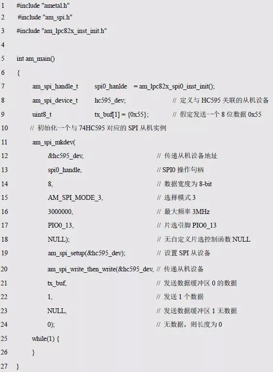
Next, you can use the message method or am_spi_write_then_write() and am_spi_write_then_read() to send and receive data. Since there are many parameters when data is sent by means of a message, the manner of using the message is not used. Because the MCU does not need to read data from the 74HC595, use am_spi_write_then_write() to send the data directly. See Listing 5.69 for details.
Listing 5.69 Sample program for driving 74HC595 output
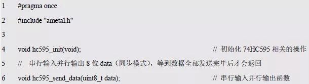
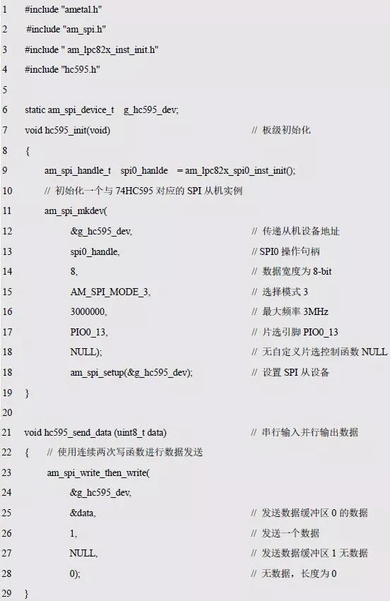
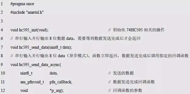
For ease of use, the 74HC595 driver can be packaged so that the 74HC595 can be used as an 8-bit I/O port expansion interface. Obviously, an initialization interface and a data output interface need to be written for the 74HC595, which are used to initialize the SPI slave instance corresponding to the 74HC595 and to output the specified 8-bit number. The declaration and implementation of the function are detailed in hc595 shown in Listing 5.70. .h and hc595.c as shown in Listing 5.71.
Listing 5.70 hc595.h interface file
Listing 5.71 hc595.c Implementation File
Based on the 74HC595 data transmission function, you can use the 74HC595 to drive the digital tube display to save pins. Consistent with the I/O driver digital tube, the software timer is used to automatically scan the digital tube. See Listing 5.72 for details.
Listing 5.72 adds new software timer related functions
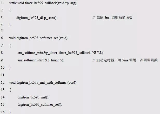
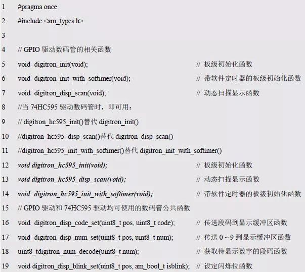
Similarly, add the new code to digitron1.c and add its corresponding function interface to digitron1.h as shown in Listing 4.27, as shown in Listing 5.73.
Listing 5.73 digitron1.h file contents
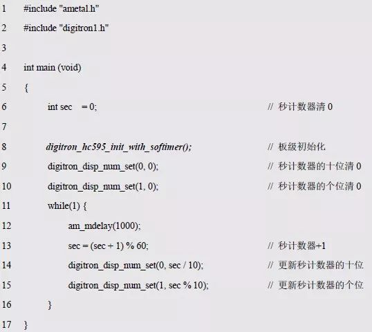
Obviously, the program is basically the same as the previous code, except that the scan function of the callback function call has changed. The test program is detailed in Listing 5.74.
Listing 5.74 Test Software Timer Auto Scan
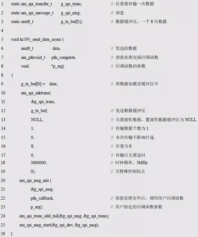
Since the callback function runs in the interrupt environment, am_spi_write_then_write() will not return until the data has been sent, so it is blocking, so the hc595_send_data() that calls this function cannot be used in the interrupt environment. In order to implement a non-blocking (asynchronous) data transfer function, the data can be sent using SPI messages. To distinguish from the previous hc595_send_data(), name it hc595_send_data_async(), as shown in Listing 5.75.
Listing 5.75 Example of the hc595_send_data_async() function
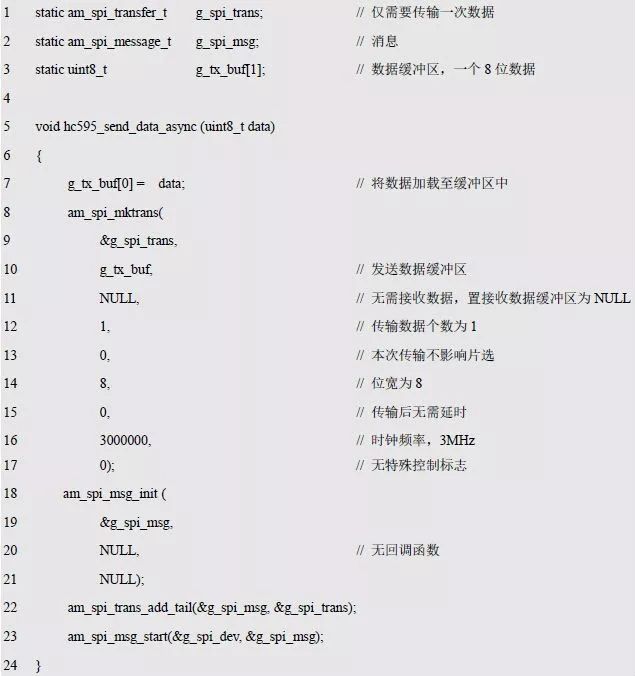
When sending data, first save the data data in g_tx_buf. Because the function is asynchronous when sending data using SPI messages, it will return immediately. After the function returns, the address space is released because data is a local variable. When the driver obtains the data to be sent, it takes the data in the address indicated by the buffer, so it must be guaranteed that the buffer is valid throughout the data transmission process. This uses a global variable to hold the data so that the buffer is always valid. Why not use the am_spi_write_then_write() function to do this? Because this function is synchronous, it will wait until the data is sent, and the address of data is valid and will not be released during the entire data transmission.
Is such an asynchronous transfer function feasible? If the user calls the function at a long interval, the previous data transfer has been completed correctly before each call, and the data can be sent normally without problems. However, if the time interval is very short, for example, calling the function twice to send two data in succession will cause the previous transfer to be overwritten, causing a serious error. A callback function can be added like an SPI message. When the data is sent, the callback function is called to notify the user that the data has been sent. Since the message itself has this feature, you only need to directly pass the callback function passed by the user as the callback function parameter initialized by the SPI message. See Listing 5.76 for details.
Listing 5.76 Modifying the hc595_send_data_async() function
For subsequent use, the declaration of the function is stored in hc595.h as shown in Listing 5.70, as detailed in Listing 5.77.
Listing 5.77 hc595.h file contents
After the asynchronous data transmission function is implemented, data can be transmitted in an interrupt environment. Obviously, using the software timer to automate the digital tube scan needs to modify digitron_hc595_disp_scan() to make it call hc595_send_data_async(). It is advisable to use a flag bit. When the flag is set to 1, the transfer is complete. See Listing 5.78 for details.
Listing 5.78 Modifying the digitron_hc595_disp_scan() function (1)
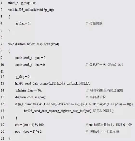
The program uses the g_flag variable to indicate whether the shadow segment code is over or not. At first glance, there is no problem. This is a general programming method. But it did make a very serious mistake, because the function directly uses the blocking while() loop wait statement, although hc595_send_data_async() is asynchronous, but after adding the wait statement, it will scan the function again.
It becomes obstructive, so the scan function is still not available in an interrupted environment.
Scanning the digital tube firstly needs to transmit the blanking segment code (0xFF), then determine the corresponding bit selection, and then transmit the display segment code, which will call the segment code transfer function twice in a very short time (the image segment code and The segment code displayed). Obviously, the block segment code cannot be transmitted without displaying the segment code. Since the callback function is called after the block segment code is transmitted, why not put the subsequent code into the callback function of the completion of the block segment code transfer? See Listing 5.79 for details.
Listing 5.79 Modifying the digitron_hc595_disp_scan() function (2)
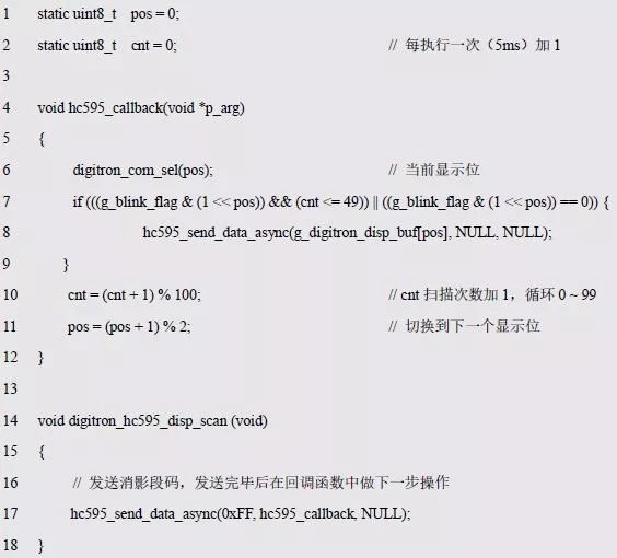
The program simply divides the previous scan function into two parts, and puts the content after the elimination of the segment code into the callback function, which solves the problem of waiting for the transmission of the segmentation code. Then, if you send the segment code that is displayed normally, do you still need to wait for it to end? In fact, after the normal display of the segment code transfer is completed, no further operations are required, so the callback function does not need to be set. If you do not use the callback function to determine whether it has been transferred, then if it is scanned again, it will not be completed due to the last message processing.
And what is wrong? The next scan is after 5ms. Due to the fast SPI transfer rate, it takes only a few microseconds to transfer 8-bit data at a rate of 3MHz, so 5ms is enough time for the transfer to complete, thus ensuring the normal display of the segment code transfer on the next transfer. The data was successfully completed before. The modified function that uses the software timer to implement automatic scanning, because the interface has not changed, only modified the implementation, so you can directly use the sample program of Listing 5.74 to test.
5.6 I 2 C bus
In most cases, the MCU communicates with the I 2 C slave as an I 2 C master, so only the interface functions associated with the I 2 C host in AMetal are described here.
> > > 5.6.1 Initialization
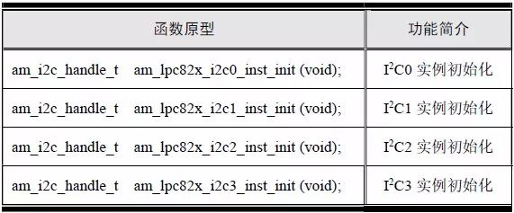
Before using the I 2 C universal interface to transfer data, I 2 C initialization must be completed to facilitate the acquisition of the I 2 C instance handle. In the LPC824, the external support of the I 2 C function is supported: I 2 C 0, I I 2 C 1 , I 2 C 2 and I 2 C 3, and each I 2 C peripheral provides a corresponding instance initialization function. See Table 5.15 for details.
Table 5.15 I 2 C instance initialization function (am_lpc82x_inst_init.h)
These functions return an I 2 C instance handle of type am_i2c_handle_t , which will be used as an argument to the handle parameter in the I 2 C generic interface. The type am_i2c_handle_t(am_i2c.h) is defined as follows:

Because the I 2 C instance handle returned by the function is only passed as a parameter to the I 2 C generic interface, there is no need to do anything else with the handle, so there is absolutely no need to know anything about the type. Note that if the value of the instance handle returned by the function is NULL, indicating that the initialization failed, the instance handle cannot be used.
If I 2 C 0 is used, the I 2 C 0 instance initialization function is directly called to obtain the corresponding instance handle:

> > > 5.6.2 Interface Functions
In AMetal, the relevant interface functions of the MCU as an I 2 C master communicating with the I 2 C slave device are detailed in Table 5.16.
Table 5.16 I 2 C standard interface functions
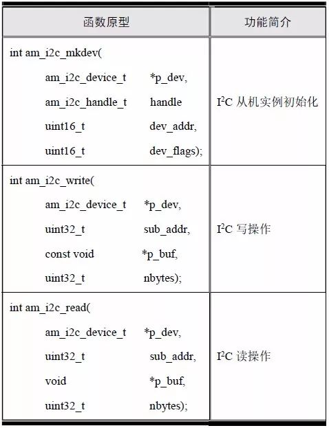
1. Slave instance initialization
For the user, the purpose of using I 2 C is to directly operate a slave device, such as LM75, E2PROM, etc. The MCU communicates with the slave device as an I 2 C master, and needs to know information about the slave device, such as the I 2 C slave address. This requires defining an instance corresponding to the slave device, the slave instance, and using the relevant information to complete the initialization of the slave instance. The prototype of the slave instance initialization function is:
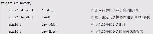
Where p_dev is a pointer to an am_i2c_device_t type (am_i2c.h) I 2 C slave instance defined as follows:

You do not need to know the specific content of the type definition when using it. You only need to use this type to complete the definition of an I 2 C slave instance:

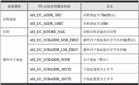
Where dev is a user-defined slave instance whose address is passed as an argument to p_dev. Dev_flags is a related attribute flag for a slave instance and can be divided into three major categories: the number of bits in the slave address, whether to ignore the number of bytes in the no-acknowledgement and in-device subaddress (also commonly referred to as the "register address"). The specific available attribute flags are shown in Table 5.17. You can use the “|†operation to connect multiple attribute flags.
Table 5.17 Slave Device Attributes
See Appendix 5.80 for examples of usage.
Listing 5.80 am_i2c_mkdev() sample program
2. Write operation
The function prototype for writing data to the subaddress specified by the I 2 C slave instance is:
If the return value is AM_OK, the write data is successful; if the return value is another value, the write data fails. The sample program is detailed in Listing 5.81.
Listing 5.81 am_i2c_write() usage example
3. Read operation
The function prototype for reading data from the subaddress specified by the I 2 C slave instance is:

If the return value is AM_OK, it means that the data is read successfully; if the return value is other value, it means that the data reading fails. The corresponding sample program is shown in Listing 5.82.
Listing 5.82 am_i2c_read() usage example
> > > 5.6.3 I 2 C expansion interface
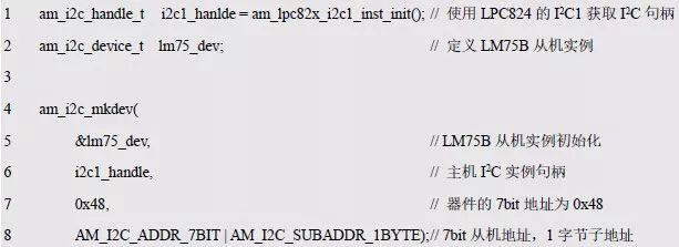
Before using the am_i2c_read() function, you need to initialize the I 2 C slave instance corresponding to the LM75B with am_i2c_mkdev() to facilitate the LPC824 to read the temperature value. When you initialize a slave instance, you also need to know two important pieces of information: the device slave address and the instance properties.
The slave address of the LM75B is 7 bits, 1001xxx, where the address bits 0~2 correspond to the A0~A2 of the hardware connection. Since A0~A2 are all connected to ground, the value of xxx is 0, and the slave address of LM75B is 0x48.
Instance attributes can be divided into slave address attribute, response attribute and in-device sub-address attribute. The slave address of LM75B is 7 bits, and its corresponding attribute flag is AM_I2C_ADDR_7BIT. If the slave instance cannot answer, set the AM_ I2C _IGNORE_NAK flag. In general, a standard I 2 C slave instance can generate an acknowledgment signal that is not required unless otherwise stated.
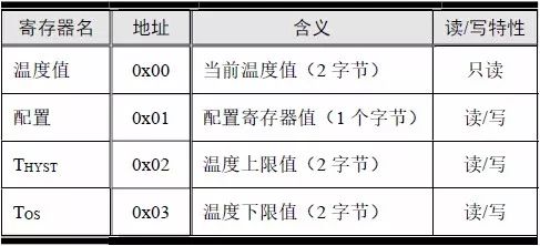
The LM75B has a total of 4 registers, as shown in Table 5.18. Since the address of the register is 8 bits, the subaddress in the device is one byte, and the corresponding attribute flag is: AM_I2C_SUBADDR_1BYTE. Since there is only one byte, there is no distinction between the high byte and the low byte, and the AM_I2C_SUBADDR_MSB_FIRST or AM_I2C_SUBADDR_LSB_FIRST flag is not required.
Table 5.18 Register Functions
Example code for initializing an LM75 slave instance using am_i2c_mkdev() is shown in Listing 5.83.
Listing 5.83 initializes an I2C slave instance corresponding to the LM75
After initializing the slave instance, you can use am_i2c_read() to read the temperature value. As shown in Table 5.18, the temperature value is stored in the register with address 0x00, contains the temperature value of two bytes, and is read-only. Therefore, you can directly use am_i2c_read() to read the two-byte content whose subaddress is 0x00, that is, the temperature value. For details, see Listing 5.84.
Listing 5.84 Reading Temperature Values

What is the temperature value represented by the two bytes of data read? The meaning of the temperature values ​​specifically represented by these two bytes can be obtained from the chip's data sheet. The temperature is expressed in double-byte 16-bit twos complement, stored in byte 0 and byte 1, respectively, and the byte 0 data is first read. The integer part of the temperature is stored in byte 0, and the fractional part of the temperature is stored in byte 1, only the upper 3 bits are valid, so the resolution of the temperature is 1/23 = 0.125 °C.
If you combine byte 0 and byte 1 into a 16-bit signed integer, the 16-bit signed integer is 256 (28) times the actual temperature. If your system supports floating point numbers, use the following formula to get the current temperature value:
Current temperature value (float variable) = (value of byte 0 × value of 2 8 + byte 1) / 256.0
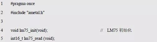
In an MCU without a hardware floating-point unit, such a formula is very computationally inefficient. In actual use, it is generally not necessary to obtain the temperature value of the floating point number, and only a little processing can be used. For example, for the digital tube to display the temperature value, it is only necessary to display the integer part of the temperature value (indicated by an integer) and the fractional part (indicated by an integer), and it is not necessary to calculate the floating point number. The interface function declaration for the LM75 is detailed in Listing 5.85.
Listing 5.85 LM75 Interface (lm75.h)
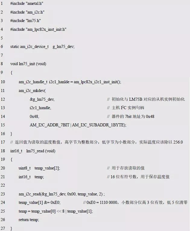
Among them, the role of lm75_read() is to read the LM75 temperature value, and its return value (16-bit signed number) is 256 times of the actual temperature. The corresponding implementation (lm75.c) is shown in Listing 5.86.
Listing 5.86 Implementation of the LM75 Interface (lm75.c)
In the background of the public number, reply to the keyword [ programming ], you can read the two books "Programming for AMetal Framework and Interface (Top)" and "Programming and Data Structure".
The Taobao purchase link for books is as follows, can be copied to the browser to open:
[Guangzhou Zhiyuan Electronic Official Enterprise Store], copy this information ¥ Ebic03xkccD¥ and open the mobile phone Taobao
Extended readingZhou Ligong: In- depth understanding of AMetal - keyboard scanning interface and PWM interface
Zhou Ligong: In-depth understanding of AMetal - LED digital tube interface
Zhou Ligong: In-depth understanding of AMetal - interface and implementation
Zhou Ligong: Interface-Oriented Programming - SPI Bus and IIC Bus
Zhou Ligong: Interface-Oriented Programming - Event Driven and Keyboard Management
Zhou Ligong: Interface-Oriented Programming - LED Digital Tube
Zhou Ligong: Interface-Oriented Programming - Platform Technology, Switching Signals
Zhou Ligong: PWM realizes DAC circuit design
Zhou Ligong: ADC Signal Conditioning Circuit Design Necessary Measures, Measured Verification and Application Notes
Zhou Ligong: ADC signal conditioning circuit design application background and circuit design
Zhou Ligong: Introduction to MicroPort Module and Description of MiniPort Module
Zhou Ligong: Application of Switch Matrix (SWM) and AM824-Core
Zhou Ligong: Know the LPC824 and LPC84x microcontrollers
New Book Express | Prof. Zhou Ligong's new work "Programming for AMetal Framework and Interface (I)"
New Book Catalog | Prof. Zhou Ligong's new work "Programming for AMetal Framework and Interface (I)"
Exclusive sale | Zhou Ligong's own book "Programming for AMetal Framework and Interface (I)" (book version)
Public number introduction
Zhiyuan Electronics official WeChat public number, a research and development test sharing platform of 500 engineers, to provide you with leading product technology and solutions in the electronics industry .

POWER-D & COMBO-D D-SUB CONNECTORS
The ANTENK POWER-D & Combo-D mixed contact d-sub connectors are designed for rugged / robust applications where both power & signal are required from a single connection. Featuring [Solid-Pin" machined contacts, these connectors offer high reliability performance for the most challenging design applications.
Combination D-SUB Connectors provide the ideal solution for applications to require power, signal and coaxial connections within one connector. This series of connectors achieves space saving on PCB`s and I O designs.
Within this product family are various pin out configurations possible. Almost endless selections can be created mixing power, signal and coaxial contacts.
Power contacts from 10 amp to 40 amp current handling. Signal contacts in various styles complete the product offering.
Industry standard terminations types, solder cup, PCB contacts in straight and angled pin configurations. Crimp types and wire wrap contacts.
POWER-D & COMBO-D D-SUB CONNECTORS characteristics:â– Space savings on the PCB
â– Different wire terminations are possible in a single connector
â– Cost savings - mixed layout
â– Insertable and removable coaxial, power, high voltage and signal contacts
â– Precision machined contacts
â– Various quality classes are available
â– Wide product range
A wide range of standard pin configurations fully loaded with signal contacts are available. Specially configured contacts with power, coaxial and signal contacts can be constructed.
D sub power connector Applications
Communications
Base Stations
Switching
Transmission
Asymmetric Digital Subscriber Line (ADSL)
Data
Desktops/ Laptops
UPS, Storage systems
Routers, Servers
Printers, Copiers
Consumers
Consumer Electronics
Set-top-boxes
Energy meters
Industrial & Instrumentation
Robotics
Control Drives
Power Supplies
Medical Instruments
Test Equipments
POS & Handheld terminals
Renewable Energy
Surveillance Camera
Office Automation
Parking Meters
Gaming Machines
Combo Power D-sub Connectors,RJ45 3U Gold,Gold Flash Plated,8P8C with Shield,Shield with EMI
ShenZhen Antenk Electronics Co,Ltd , https://www.antenksocket.com