Application of embedded DSP in home appliances
| Overview DSP is good at mathematical operations. The embedded DSP motor control chip integrates the DSP core with a series of powerful control peripherals on one chip, so that the fast DSP core can be used as the calculation engine, plus the on-chip A/D. The module increases motor control bandwidth and allows for more complex scale control and sensorless algorithms at low cost, thus enabling control of AC induction motors, brushless DC motors and switched reluctance motors without the need for speed or position sensors, or even special Current sensing method. These computing powers and optimized peripherals make it easy to perform more functions, such as power factor correction; to meet the requirements of certain special applications, such as the balance control of the washing machine, without increasing the cost of the controller. The new economy will bring us into a world of all-digital, more digital information will flood into the family, such as the Internet refrigerator is a quantitative example. Embedded DSPs make it easy to establish communication between controllers and even appliances. The latest embedded DSP with JTAG for debugging and CAN bus for home network control. The DSP Compute Engine will integrate with more advanced peripherals to provide a single-chip solution. So optimized peripherals are programmable and under real-time control of the software, so embedded DSPs offer more flexible control features and are easy to upgrade.  This article will start with the basic features of the embedded DSP motor control chip, and introduce the DSP-based field oriented control and extended Kalman filter algorithm. Embedded DSP motor control chip Different manufacturers have different DSP motor control chips in DSP cores, peripherals, programming languages, and other semiconductor technologies. The advanced DSP core combined with optimized peripherals can be used not only for motor control, but also for communication and other power electronic controls. Because of the large differences in peripherals between applications. It is uneconomical and unrealistic to design an embedded motor control chip for all applications. Often, there are a range of products optimized for different applications. The peripherals shall include at least 3 to 6 phase 16-bit PWM generators, multiple auxiliary PWM counters, analog acquisition systems, reference voltages, serial communication ports, general purpose I/O ports, and may also include a programmer interface, a CAN bus, and JTAG interface, DMA controller, DPI port, etc. Some embedded DSPs have on-chip flash memory, such as ADI's DashDSP family. Software can be easily modified through PC and DSP communication at different stages of product development for easy reprogramming. Flash memory software can be ported to ROM-based products for mass production. The PWM module provides a flexible, programmable multiphase PWM waveform that can be used to drive an AC induction motor, a brushless DC motor, or a switched reluctance motor. The auxiliary PWM output can be used to provide front-end power factor correction or Switching Power Supply control. In addition, it can also be used as a simple A/D conversion through an appropriate filtering network. The embedded DSP motor control chip uses an A/D system with single integral, total incremental or flow flash technology. Its multi-channel analog sampling system typically has a resolution of 10 to 12 bits, depending on the different models selected for different applications. Sensorless Control of Brushless DC Motor Using Extended Kalman Prediction Algorithm Compared with AC induction motors, brushless DC motors have many advantages due to their characteristics closer to brushed DC motors. At the same time, because brushless DC motors mostly use permanent magnet rotors, they have higher efficiency, so the characteristics are suitable. For household appliances. It is born with the characteristics of stable rotation, low noise and small motor size. It also makes it favored by many household appliances manufacturers. In fans, washing machines, refrigerators and air conditioner compressors, it has started to use brushless DC as much as possible. . Brushless DC motors are controlled differently from brushed DC motors or AC induction motors. They require some position sensing information to select the correct commutation sequence, while home appliances are cost sensitive, which increases the number of sensing components. The extra cost is unacceptable and unrealistic; at the same time it is easy to reduce the reliability of the system, and for a brushless DC motor like a compressor, the installation of the position sensor is very unrealistic and is not allowed. In this case, the sensorless control of the brushless DC motor will be widely adopted, making it a hot topic in the field of home appliances. There are a variety of algorithms that can achieve sensorless control. The traditional method (zero-crossing detection method) mostly uses the zero-crossing point of detecting the non-conducting opposite potential to judge the position of the rotor, and selects the best commutation according to the zero-crossing information and the commutation logic. order. These methods have been adopted in many home appliances, such as DC inverter refrigerators and DC inverter air conditioners. However, since the zero-crossing detection method can only detect some specific points, and as the motor speed changes within a wide range, the variable frequency of the back-EM potential will also change, and the filter components in the detection circuit will bring a certain phase shift, which will It greatly affects the accuracy of detecting zero crossings. At the same time, due to the reverse current of the freewheeling diode on the power device, it will also have a certain influence on the detection of zero crossings under high current conditions. Aiming at these problems, the extended Kalman prediction algorithm is used to estimate the instantaneous position and velocity information of the brushless DC motor rotor, which provides a better solution for sensorless control of brushless DC motor. Moreover, using the embedded DSP motor controller of ADI of the United States, only a 28-pin ADMC328 is needed to implement the algorithm conveniently. Figure 1 shows the block diagram of estimating the rotor angle (position) and speed of a brushless DC motor using the extended Kalman prediction algorithm (EKE). The dotted line frame is an embedded DSP motor controller, and the three pairs of resistor networks are used. The back EMF signal of the non-conducting phase is measured and sent to the ADC terminal of the embedded DSP motor controller. It can be seen from the figure that the method adopts double closed-loop control, and the EKE algorithm is used to estimate the rotor speed of the motor, and the outer loop is closed loop to realize the speed loop control. At the same time, the rotor position can be estimated to achieve sensorless commutation without relying on zero crossing detection. A sampling resistor can be used on the DC bus to measure the current in the conducting phase as internal loop feedback for current (torque) control. When recursive processing is performed in the DSP, the EKE algorithm estimates the rotor speed and position to become the back EMF noise input. It consists of two steps: the first step is to use the state quantity and the pre-estimation based on the previous state quantity output; The step is to complete the calibration process, using the back EMF measurement data and the observer model to optimize the correction of the previously estimated state quantities. To complete the EKE algorithm, you first need to build a continuous time domain system model. In this application, the linear system model can be described by equation (1): X=Fx+Gu (1) The continuous time domain system model can be transformed into a discrete-domain linear system model. The discrete-domain system model is obtained by sampling the continuous time-domain system model at a sampling frequency equivalent to twice the PWM frequency. X(k+1)=φkXk+Γkuk+σk (2) Here, the state vector where ωk, σk are two-dimensional discrete state variables representing the rotor velocity and angle (position) included in the system; uk is the torque signal, which can be a deterministic input; system random interference (model noise) σk is zero Mean white Gaussian noise, defined by its covariance matrix. In this application, only the observer model is non-linear, which can be described as follows: Zk=hkXk+Vk (3) Here hk is a nonlinear function, which should be the closest approximation of the back EMF of the non-conducting phase, involving rotor position and velocity - the state variables of the system. The measurement noise is zero-mean white Gaussian noise, and its covariance matrix is ​​defined as Rk. In EKE, the nonlinear observer model can be linearized at the latest state prediction point. If the nonlinear function is sufficiently smooth, it can be expanded into Taylor series at the latest state point, which ensures that the existing linear approximation is the best approximation for the observer model, and the selected trajectory is also the most recent trajectory. . The determination of this function plays a key role in whether the EKE algorithm can get correct predictions. The state quantity is estimated in advance by equation (2), and the predicted value is obtained by ignoring the model noise and then adding the pre-estimated value to the measurement residual corrected by the Kalman gain Kk weight, which can be expressed as follows: Xk=xk+Kk(zk-zk -) (4) In order to get the best estimate in (4), the following Kalman gain is used: Kk=Pk -HkT(HkT+Rk) -1 (5) The entire recursive process can be described by the scale flow chart shown in Figure 2. Obviously, the EKE for rotor speed and angle estimation is actually a DSP algorithm. The discrete measurement of the back EMF is processed by the DSP into an optimal estimate of the rotor speed and angle. It can be linearized by a linear trajectory. The recursive process predicts (xk+1)- with the optimal estimate Xk as the reference value at time tk of x. Therefore it is actually an approximately optimal filter design, often referred to as suboptimal filtering. The execution of the EKE algorithm involves a large number of matrix operations that can be easily processed with an embedded DSP motor controller. 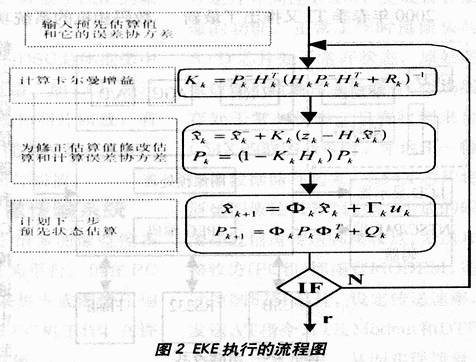 |
:
0 times
Window._bd_share_config = { "common": { "bdSnsKey": {}, "bdText": "", "bdMini": "2", "bdMiniList": false, "bdPic": "", "bdStyle": " 0", "bdSize": "24" }, "share": {}, "image": { "viewList": ["qzone", "tsina", "tqq", "renren", "weixin"], "viewText": "Share to:", "viewSize": "16" }, "selectShare": { "bdContainerClass": null, "bdSelectMiniList": ["qzone", "tsina", "tqq", "renren" , "weixin"] } }; with (document) 0[(getElementsByTagName('head')[0] || body).appendChild(createElement('script')).src = 'http://bdimg.share. Baidu.com/static/api/js/share.js?v=89860593.js?cdnversion=' + ~(-new Date() / 36e5)];
24V Switching Wall Charger

About this item
-
Input: AC 100-240V 50/60Hz; Output: DC 24V Switching wall charger
-
Plug Type: DC Plug 5.5 x 2.1mm;AC Plug US Plug, Cable Length: 1.2m /1.5m
-
Dimensions (WxLxH): 4.7" x 2" x 1.5", Small and lightweight for convenience, portability and storage. Easy to take anywhere!
-
Built-in protection of over current, over voltage, short circuits
-
This Power Adapter can ensures consistent power and reliable performance for your devices. Can work for 5050 3528 LED Strip 3D Printer CCTV Security System LCD Monitor.
24V Switching Wall Charger
About this item
- Input: AC 100-240V 50/60Hz; Output: DC 24V Switching wall charger
- Plug Type: DC Plug 5.5 x 2.1mm;AC Plug US Plug, Cable Length: 1.2m /1.5m
- Dimensions (WxLxH): 4.7" x 2" x 1.5", Small and lightweight for convenience, portability and storage. Easy to take anywhere!
- Built-in protection of over current, over voltage, short circuits
-
This Power Adapter can ensures consistent power and reliable performance for your devices. Can work for 5050 3528 LED Strip 3D Printer CCTV Security System LCD Monitor.
24v wall charger,24v dc adapter,24v ac dc adapter,24v switching adapter,100-240V AC to DC 24V 3A 72W Power Adapter,12W Ac Switching Power Adapter,24V 0.5A Power Supply For Led Lights
Shenzhen Waweis Technology Co., Ltd. , https://www.laptopsasdapter.com