Design and Implementation of Multi-channel Temperature Acquisition System Based on MAX6675
K-type thermocouple is a kind of temperature sensor commonly used in industrial production and scientific experiments. It can directly measure liquid vapor, gas medium and solid surface temperature in the range of 0~1 300°C in various productions. Due to its measurement range and its high cost performance, K-type thermocouples are widely used. However, K-type thermocouples have problems such as nonlinearity and cold compensation, especially when dealing with compensation problems, which require a high cost and are difficult to achieve good results. Therefore, the MAX6675 temperature acquisition chip described in this article compensates for the above defects of the K-type thermocouple. Combining the MAX6675 and K-type thermocouples for industrial production and experimentation brings many conveniences to the project and reduces the cumbersome additional circuitry. This paper presents the CPLD-based multi-channel temperature acquisition system circuit, internal logic design module, error analysis and experimental statistical report, as well as the application process and performance report of the MAX6675 multi-channel temperature acquisition system.
1 Introduction to MAX6675The MAX6675 is a serial K-type thermocouple analog-to-digital converter with cold junction compensation, linearity correction, and thermocouple disconnection detection from Maxim, USA. It has a temperature resolution of 0.25 °C and a cold junction compensation range of -20 °. +80 ° C; operating voltage is 3.0 ~ 5.5 V.
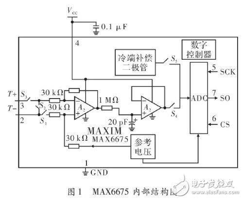
According to the thermocouple temperature measurement principle, the thermoelectric potential of the thermocouple is not only related to the temperature of the measuring end, but also related to the temperature of the cold end. In the past applications, there are a variety of cold junction compensation methods, such as cold junction freezing point method or bridge compensation method, but the debugging is more complicated. In addition, due to the nonlinearity of thermocouples, methods such as microprocessor tabular methods or linear circuits have been used to reduce the measurement error caused by the nonlinearity of the thermocouple itself, but these have increased the difficulty of programming and debugging circuits. The MAX6675 laser-corrects the parameters of its internal components to internally correct the nonlinearity of the thermocouple. At the same time, the MAX6675's integrated cold junction compensation circuit, nonlinear correction circuit, and wire breakage detection circuit all bring convenience to the use of K-type thermocouples. The MAX6675 features: (1) an internal integrated cold junction compensation circuit; (2) a simple 3-bit serial interface; (3) a temperature signal that can be converted to a 12-bit digital quantity with a temperature resolution of 0.25 °C; (4) Contains a thermocouple disconnection detection circuit. The internal schematic diagram is shown in Figure 1.
The system framework is shown in Figure 2. The system uses CPLD as the core. The multi-channel K-type thermocouple and MAX6675 collect and convert the external temperature analog signal into a digital signal, and the data is sent to the CPLD for corresponding processing, and then through communication. The module transmits the data to the computer, and finally uses the computer for data statistics and processing. The communication module in the system can use different communication methods according to different engineering or experimental environments, such as serial communication, PCI transmission card, and the like. Due to engineering applications, this article uses a PCI transmission card as a data transmission method.
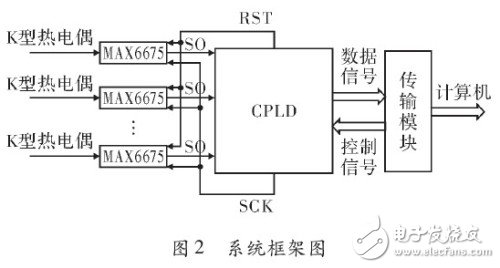
As shown in Figure 2, the K-type thermocouple transmits the acquired analog signal to the MAX6675, which converts it into a digital signal and sends it to the CPLD. The CPLD processes the data according to the timing of the MAX6675 chip to obtain the desired signal, and finally transmits it to the transmission module. The computer performs data display, statistics, and processing. So the focus of this paper is on the design of the internal logic of the CPLD. Before the internal logic design, you need to understand the working timing and principle of the MAX6675: When the CS pin goes from high to low, the MAX6675 stops any signal conversion and outputs the converted output under the action of the clock SCK. Data; when the CS pin changes from low to high, the MAX6675 will convert the next round of data. A complete data read takes 16 clock cycles and the data is read on the falling edge of SCK. The working timing diagram of the MAX6675 is shown in Figure 3.
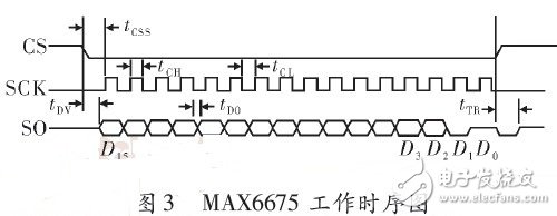
As shown in Figure 3, according to the chip manual tcss is the time when CS falls to SCK rise, the minimum value is specified as 100 ns, tCH+tCL is one clock cycle of SCK, the minimum period is specified as 200 ns, and tDV is the CS falling edge. The time of data output is specified to be no more than 100 ns. tDO is the time when SCK falls to output valid data, and tTR is the time from the rising edge of CS to the time when data stops outputting. The specified maximum value is 100 ns. According to these time regulations in these manuals, when designing the CPLD internal logic circuit, the SCK clock cycle is set to 1 000 ns or 1 MHz, tcss is set to 1 000 ns, and tDVtTR is set to 100 ns. It can also be seen that SO is 16-bit output data, in which only D14~D3 bits are temperature data, D15 bit is useless bit, D2 bit is thermocouple disconnection test bit, D1 bit is MAX6675 identifier, D0 bit is Three-state, so the 12-bit data of D14~D3 is taken out from the 16-bit data for conversion and processing. Based on the above analysis, an internal logic module as shown in FIG. 4 is designed.
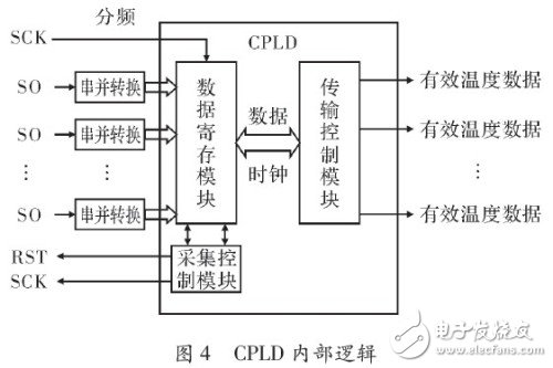
The internal logic of the CPLD is shown in Figure 4. In order to extract the 12-bit valid data, the serial SO input signal is first converted into parallel, which is beneficial to the extraction of valid data. The CLK in the figure refers to the total clock, which is clocked by a 40 MHz crystal oscillator. According to the chip data sheet and the above analysis, the SCK signal is given a frequency of 1 MHz. With the chip timing requirement, a data acquisition and data transmission is performed for the RST signal 2.5 Hz clock, ie 0.4 s. The function of the data registration module in the figure is to register the parallel input signals of each channel for later uploading. The main function of the acquisition control module is to provide the clock signals SCK and RST for the MAX6675 chip by dividing the total clock of the system. The transmission control module is useful for debugging signals during debugging. The function of this module is to add a frame header to the output signal, which facilitates the confirmation of the output signal later; and provides a reasonable synchronous clock for the transmission module, so that each data transmission can correspond to the corresponding clock.
4 post testAccording to the above principle, the hardware circuit design and the internal logic design of the CPLD are completed, and a temperature acquisition system capable of simultaneously performing multiple channels is completed. Through the multiple collection test of the temperature collection system at normal temperature, one of the temperature collection statistical charts was randomly selected as the test result, as shown in Fig. 5.
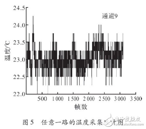
Fig. 5 is a sampling result of a total of 3 500 frames at a normal temperature for about 20 minutes. From the figure, it is first observed that the highest temperature and the lowest temperature reach 24.25 ° C and 22 ° C, respectively, and the temperature fluctuation is 2.5 ° C. In the chip manual, the temperature measurement of the chip is 0.25 ° C per data bit, and the display accuracy of the measurement is 8 data bits, so the measurement error of the chip is 8 × 0.25 = 2 ° C. At the same time, the error of the whole system, including power supply noise and circuit noise, can be considered, and the error can reach 2~2.5 °C. In summary, according to the 2.5 °C fluctuation of the temperature curve shown in Figure 5, this result is in full compliance with the requirements of the chip manual.
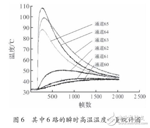
In addition, the system was tested with instantaneous high temperature. The test results are shown in Fig. 6. The data collected by 6 channels at the same time are given. The 6 line types represent 6 channels of temperature acquisition. In the graph, the range from the instantaneous high temperature is relatively close, such as channel 63 and channel 64, the change is more obvious in the first 500 frames of high temperature, reaching above 100 °C, and far from the instantaneous high temperature range, such as channel. 61 and channel 62, in the first 500 frames of high temperature, the temperature changes are more soothing. This figure clearly distinguishes the high and low temperature regions under the instantaneous high temperature strike, which fully proves the good performance of the NAX6675 and the multi-channel temperature acquisition system. .
The NAX6675 chip application and experiment verified the good performance and high cost performance of the MAX6675 multi-channel temperature acquisition system. In addition, the use of CPLD or FPGA to achieve multi-channel temperature acquisition has the advantages of simple design, small size, simple and convenient operation, less interference factors and high reliability, which has certain practical value for engineering applications.
Metal Sunglasses,Metal Frame Sunglasses,Round Metal Glasses,Metal Rim Sunglasses
Danyang Hengshi Optical Glasses Co., Ltd. , https://www.hengshi-optical.com