Detailed description of the current research status of antenna war damage
Abstract: By analyzing the literature on the existing antenna warfare in China, the antenna warfare is divided into two parts: the reflector antenna and the array antenna. The research on the array antenna is mainly the research on the phased array antenna. . The limitations of existing research are pointed out and solutions are given. The status quo of antenna warfare research and its conclusions are of great significance for the evaluation of antenna damage levels and repairs in battlefield environments.
Radars can be seen on the sea, on land, in the sky, and on satellites. It is the "clairvoyary eye" and "shunfeng ear" on the modern battlefield. It is a vital equipment in the modern information warfare. Of course, it is also an important target of the enemy on the battlefield. As a carrier for transmitting and receiving energy in electronic countermeasure equipment, the antenna system is difficult to carry out effective electromagnetic concealment due to its own radiation characteristics, and it is easy to be identified and positioned, and it is hit by enemy anti-radiation weapons [1]. Therefore, it is very important to study the battle damage of radar antennas.
1 antenna battle damageThe war damage [2] is the abbreviation of the equipment combat damage. It refers to a state in which the equipment is damaged or the function is seriously degraded due to the attack of the enemy weapon during the combat use. In the past, it was mainly caused by bullets, shells and bombs, and there were damages caused by missiles. In addition to these hard damages, the damage includes damage caused by electromagnetic waves, lasers, and the like. The antenna damages of the existing research mainly include fragment damage and shock wave damage. There are separate studies of fragment damage, such as the reference [3-9], there are separate studies of shock wave damage, such as the reference [10-11], as well as the study of fragmentation and shock wave composite damage, such as the reference [12-14] . Depending on the type of antenna, it can be roughly divided into reflective surface antenna damage and array antenna warfare. The main content of the array antenna battle damage research is the damage of the phased array antenna.
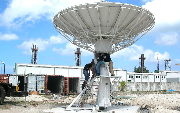
2 warfare study of reflector antennaThe damage of the reflector antenna mainly includes three types of damage [15]: feed damage, deformation of the reflective surface and perforation of the reflective surface.
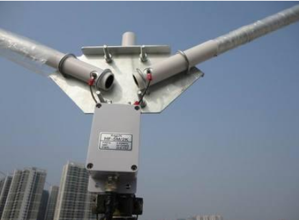
2.1 Feed damage
In most literatures dealing with antenna warfare, feeds are assumed to be intact, and there is very little research on feed damage alone. The reference [16] proposed the study of feed damage, which is the first literature in China to study feed damage. It studies the radiation characteristics of feed perforation damage, analyzes the influence of feed source damage on the secondary radiation of the reflection surface, and uses FDTD method to calculate the aperture field when the feed is intact and when it is damaged, and compares it; The PTD hybrid algorithm calculates the secondary radiation characteristics of the reflector antenna, and compares the secondary radiation characteristics of the antenna when the feed is intact and when it is damaged. It is clear that the feed damage directly affects the secondary radiation characteristics of the reflector antenna. Reference [15] simulates the single-hole and double-hole feed damage, and gives the specific parameters of the antenna performance when the feed hole is damaged and the feed is intact, and the antenna pattern is not obtained when the single hole is damaged. Symmetry, the width of the main lobe is widened, the directionality is deteriorated, and the gain is reduced.
2.2 Reflection surface deformation
The deformation of the reflecting surface is mainly caused by the shock wave. Reference [9] through the modeling and simulation of the reflector antenna, based on the simulation data to compare the impact of the impact of the antenna on the front, side and back of the antenna respectively. It is concluded that the shock wave caused by the shock wave acting on the antenna at the same distance is the largest. It can be seen from reference [17] that when the reflecting surface is deformed, the deformation position and area have the greatest influence on the electrical performance, and the closer the position is to the center, the larger the deformation area, and the greater the influence on the antenna performance. In reference [13], the reflection surface equation of the central deformation part is derived from the real experimental data, and the radiation field of the deformation part is derived, and the radiation field of the entire deformed antenna is obtained. Change the position and size to observe the change of the radiation field after deformation, and compare with the radiation field in good condition to draw the conclusion that the sidelobe elevation is serious, and give the conclusion that the edge deformation will make the pattern asymmetrical. In short, the deformation of the antenna has a great influence on the performance of the antenna, and there is no good repair measure for the time being.
2.3 reflective surface perforation
The perforation of the reflecting surface is generally caused by the intrusion of fragments having a certain initial velocity. Most of the domestic research on radar antenna warfare is aimed at the study of the impact of fragmentation on the antenna. The shape and size of the fragments are arbitrary. In the existing research, the shape of the fragments is idealized as a regular pattern such as a circle or a square, which has certain errors, and also facilitates theoretical calculation and simulation research.
The commonly used model of the reflector antenna hole [6], it is known that the far-field radiation electric field of the reflector antenna is:
Where: ω is the radiation frequency; μ is the magnetic permeability; S is the surface area of ​​the reflection surface; β is the plane wave phase constant; J(') is the surface current density; r is the distance from the source point to the far field point; Vector; r' is the vector of the feed point pointing to the point of incidence of the reflecting surface.
From this, the surface current density distribution excited on the reflecting surface can be obtained, and the radiation characteristics of the paraboloid can be obtained. According to the physical optical approximation, the equivalent current of the surface of the reflector antenna can be obtained. Since there is no current at the perforation of the damage, the current exists only in other intact surface regions, so as long as the current portion of the integrand in equation (1) is changed to equation (2):
This changes the damage model by changing the position and size and number of holes.
Xiao Jiang [2 ~ 3] separately studied the damage of the reflective surface by single hole and porous. The far-field radiation characteristics of the damaged antenna are analyzed in detail under the variable factors of the aperture and the position of the hole and the number of holes. It is concluded that the larger the aperture or the closer the hole is to the center position, the more the gain decreases, and the more the sidelobe level increases. More, the more the number of holes, the greater the elevation of the side lobes, but the overall effect is not obvious. On the basis of this, Fu Shiqi [4] carried out research on the repair method of single hole damage, proposed three effective repair methods, and compared the three methods, and obtained the most convenient and practical method in the battlefield environment. That is, the patch on the inner side of the antenna is slightly larger than the hole, which causes a certain error and the error is determined by the thickness of the patch. On the basis of the previous, Yuan Junming [5] focused on the variation of the far-field radiation characteristics of the antenna with different damage density. The results show that the effect on the gain is significant only when the damage density is large. It is difficult to cause serious damage to the antenna by simply relying on the fragment. The size, position and density of the fragment holes are the main factors affecting the electrical performance of the antenna. The impact on performance is mainly reflected in the reduction of gain, the elevation of side lobes and the deterioration of directionality. It is the main destructive factor on the battlefield.
3 array antenna researchThe most important features of an array antenna different from a reflector antenna are: better directivity and stronger radiation field strength. The array antenna is equivalent to a superposition of a plurality of electromagnetic waves. The most special one is the phased array antenna. The following mainly analyzes the battle damage of the phased array antenna.
3.1 fragment damage
The earliest study of phased array fragmentation damage in China is the reference [18], and the equivalent model of the phased array radar vulnerable parts-antenna and box is established. It is concluded that the larger the diameter of the tungsten ball fragment, the breakdown radar antenna. The conclusion that the required killing kinetic energy is larger, further infers that the damage resistance of the radar vulnerable parts to the tungsten ball fragments is significantly improved with the increase of the diameter of the tungsten ball fragments. Reference [7] established a three-dimensional model of target damage from a microscopic point of view, and specifically analyzed the parameters of the tungsten ball model and the target model. It is believed that the initial velocity of the initial velocity is greater in the impact of penetration. The larger the interaction time with the target plate is, the more the corrosion of the tungsten ball and the target plate is aggravated. Reference [19] established the damage assessment model of the phased array radar by the fragmented warhead, and calculated the vulnerability of the radar in all directions under the action of the fragmented warhead. The results show that the damage on the side of the antenna is the best. The distribution of damage probability on the off-target surface under a certain endpoint condition is calculated and the corresponding conclusion is drawn.
3.2 Shock wave damage
Reference [20] uses the theoretical analysis method to study the dynamic response of the radome under the action of the explosion shock wave. The experimental method is used to study the damage of the radome and the antenna structure under the action of the explosion shock wave, and the radome and the radiation unit are obtained under the action of different intensity shock waves. Damage and destruction. On the basis of the experiment, the numerical simulation method is used to simulate the structural equivalent model of the antenna under different shock wave intensity according to the damage characteristics of the shock wave load by using the finite element analysis software ANSYS. The numerical simulation results agree well with the experimental phenomena. Reference [10] studied the degree of damage to the target plate at different positions of the explosive, and gave a rough degree of damage according to the position of the fried point.
3.3 Composite damage of fragments and shock waves
Reference [11] studied the composite damage effect of phased array radar radome under the combined action of fragment and shock wave. Reference [12] studied the combined effects of fragmentation and shock waves on the target plate at different time series, and studied the fragmentation first after the shock wave and the shock wave first to the fragment. After simulation analysis, it is concluded that the difference between the timing of the fragment and the shock wave has a great influence on the composite damage result.
3.4 Radiation unit failure
In reference [21], the magnitude of the failed array element is set to “0â€, and the remaining array elements are superimposed to obtain the antenna pattern; the model of the phased array antenna is established, and the uniform array elements are respectively invalidated and partially The antenna failed and the antenna was simulated when it was intact. The conclusion is as follows: the more the array element fails, the more obvious the antenna directivity coefficient decreases, and the sidelobe elevation; when the number of failure array elements is the same, the uniform failure is much lower than the local failure directivity coefficient, and the sidelobe elevation is less; When the number of failed array elements is the same, the central partial failure is less than the directional coefficient of the edge partial failure, and the highest sidelobe elevation is obvious. These conclusions have important implications for the study of phased array warfare.
4 Limitations and solutions in existing researchIn the study of fragment damage, the fragment shape was regular and the fragment size was the same in the same simulation. However, in the actual battlefield environment, the fragment shape is irregular and cannot be replaced by the same size of the regular shape. At present, the research on simulation is more mature and common, and there are many aspects of the research on the bomb after the explosion. Modeling and simulation can be carried out according to the shape and size of the fragments in the actual explosion after the explosion, and a fragment database of different shapes and sizes can be created, and the fragments of different shapes and sizes can be simulated in the same simulation. Based on the existing research, the corresponding expansion is carried out, and the simulation results closer to the actual combat environment are obtained, and how to repair the broken holes simply and efficiently in the battlefield environment is further studied. At present, the only repair method for the damage of the broken hole is only the repair of the circular broken hole, and on this basis, more repair methods for the actual situation can be proposed.
The deformation has a great impact on the reflector antenna, but there is no good compensation method. Or we can learn from the repair method of fragment damage, make patches of various sizes from small to large according to the curvature of the antenna, put the corresponding patches on the deformed position, and then carry out simulation research on the antenna with the patch attached. Repair effects, errors, etc.
There are few researches on the battle damage of phased array antennas, and the cost of T/R components will decrease as the various process technologies are skillful. Due to the inertial scanning of phased array, flexible beam pointing, multi-beam simultaneous realization of different functions, high reliability, etc., its battle damage research will also have important significance. In this paper, the research on phased array damage is divided into four kinds, and the actual situation is complicated. The damage of the radome also has an influence on the radiation characteristics. In actual combat, damage to the feeder caused by fragmentary shock waves is not ruled out. In the subsequent research, the damage caused to the various parts of the antenna in the battlefield environment can be considered in all aspects. Due to the adjustable amplitude and phase of each phase element of the phased array antenna, this feature can be used in later studies to adjust the radiation characteristics of the phased array antenna.
In general, shock waves cause greater damage to the antenna and are more difficult to repair. If the shock wave is far away from the antenna, it will not cause too much damage. Fragmentation is the main cause of damage to the antenna on the battlefield. It is an important aspect of war damage research, but a few fragments do not cause too much damage. The existing fragments and shock waves have important value for the study of the composite damage caused by the antenna, which is close to the actual environment of the battlefield. In short, the research on antenna warfare has certain guiding significance for the antenna damage assessment and repair of the actual battlefield.
CL-2H Copper Connecting Terminals
Our company specializes in the production and sales of all kinds of terminals, copper terminals, nose wire ears, cold pressed terminals, copper joints, but also according to customer requirements for customization and production, our raw materials are produced and sold by ourselves, we have their own raw materials processing plant, high purity T2 copper, quality and quantity, come to me to order it!
CL-2H Copper Connecting Terminals
Taixing Longyi Terminals Co.,Ltd. , https://www.lycopperlugs.com